Aerospace deep hole drilling can establish a shaft centerline, remove material from a forging or produce an internal contour. These tasks impose different demands on the installation. The UNISIG aerospace description names all three roles and describes landing-gear forgings with extended arms or lugs.
A cylindrical bore does not imply a cylindrical blank
An extended lug affects the space needed to hold and move the part even when the bore itself is straight. UNISIG discusses fixtures, equalization and machine swing for these forgings. This explains why a bore diameter and length alone do not describe the machine envelope.
For a feasibility review, show the incoming forging outline beside the bore axis. Mark the proposed access direction and the external features used to locate the part. A finished-part model can hide excess material that exists during drilling; keep the manufacturing stage in the model name.
Internal contouring asks a different question
The same source describes CNC bottle boring for internal contours. A straight hole establishes an opening, while internal contouring changes the wall profile within it. Those are separate geometric deliverables, even when the equipment portfolio includes both.
A process comparison should therefore identify whether it ends with a drilled opening or with the specified internal profile. Comparing those outputs through one cycle-time number would obscure the extra work. Where material has been removed for weight reduction, the final wall relationship needs its own drawing-based observation.
Link the axis to the features that use it
Our suggested inspection map distinguishes the measured bore from its external reference features. A local diameter observation does not identify the relationship to a bearing seat, lug or other specified datum. Keep those relationships beside the relevant measurement rather than describing all of them as precision.
If another operation changes the external surface after drilling, retain the stage of the earlier report. The report may remain useful for process control while final acceptance requires a later relationship measurement. This is an interpretation of the manufacturing sequence, not a universal aerospace tolerance.
Read a real installation before transferring its result
The linked ALTA Precision report supplies a named landing-gear installation to examine. Its supplier-reported result belongs to that application. Use it to understand the workholding problem, then return to the actual forging and inspection requirement for a new part.
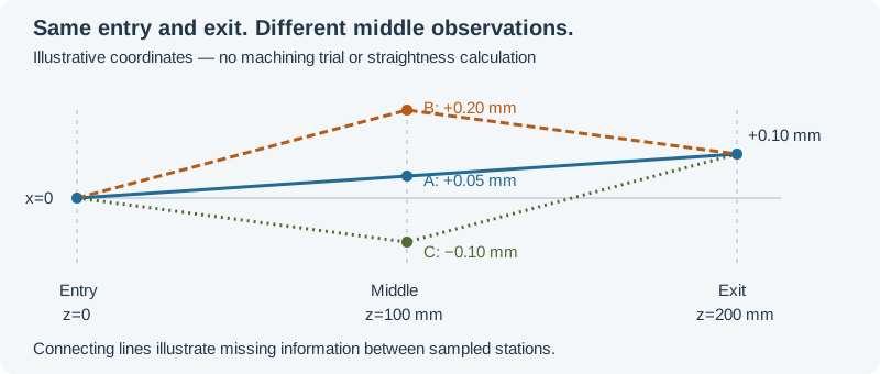
The coverage diagram below makes the reference and observed region visible. The bore-quality worksheet helps record those fields. Continue to the ALTA case for the installation, or internal profiling for the distinction between an opening and a finished contour.
Revision note
October 8, 2026: revised the technical explanation and connected reading after source review. Original publication date and URL retained.