Mold and die deep hole drilling connects waterline geometry to the rest of the tool. UNISIG’s mold-machine description discusses milling and drilling on one platform, compound-angle holes and multi-side positioning. These are manufacturing arrangements; a positionable straight drill does not by itself create a curved internal passage.
Keep the cavity and the waterline in one model
A bore can be correctly made along its programmed axis while its relation to the cavity is wrong. Our suggested model review therefore shows the cavity, waterline centerline and external entry together. Identify the model revision used for programming rather than relying on a detached list of hole coordinates.
Where passages intersect, retain the intended junction. The entry location and final depth do not on their own demonstrate that the complete connected flow path matches the drawing. Plan the observation or test for that junction as a separate feature.
Fewer setups is an equipment claim with a boundary
UNISIG describes combined milling/drilling arrangements and different spindle architectures. These may change handling and setup requirements for a proposed job. A quoted benefit still needs the actual part, operation sequence and timing boundary before it becomes a complete cost comparison.
If the workpiece is moved between machines, identify the retained reference. If it remains on one platform, document which operation changed the cavity or bore before final inspection. The machine count is useful information but does not replace a feature relationship measurement.
Thermal performance is a different result
Fraunhofer IWU’s hot-stamping project describes limits of conventional drilled or segmented cooling arrangements and investigates an additively manufactured network close to the tool contour. That project concerns hot stamping and its stated test configurations.
Its cooling result should not be attached to an unrelated straight-drilled injection mold. A new thermal comparison needs the actual channel topology, tool and process conditions. Measuring a bore dimension and measuring heat removal answer different questions.
Follow geometry into programming and inspection
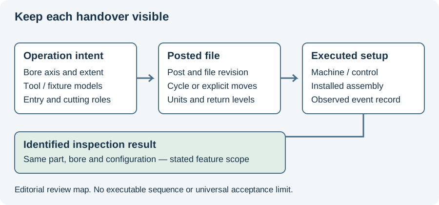
The program-evidence diagram below connects a model revision to the executed machining record and observed feature. The RFQ worksheet can hold the passage and delivered-stage description. Continue to the cooling-topology article for straight versus conformal geometry, or the CAM guide for preserving the relationship between model, program and executed part.
Revision note
October 8, 2026: revised the technical explanation and connected reading after source review. Original publication date and URL retained.