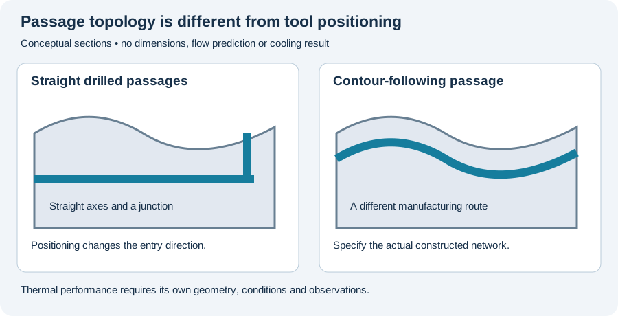
Gun-drilled cooling channels and conformal cooling describe different aspects of a tool. Gun drilling identifies a machining method; conformal describes the relationship of a passage to a contour. Fraunhofer IWU’s hot-stamping project explicitly distinguishes conventional deep-drilled or segmented arrangements from a laser-melted network close to the tool surface.
An angled straight hole remains a straight hole
UNISIG’s mold page describes compound-angle drilling and multi-side positioning. These expand the directions from which a straight passage can be made. They do not mean that the rotating drill follows a curved internal path.
The topology sketch below illustrates that distinction. It is an editorial geometry example without dimensions or calculated thermal performance. Intersecting straight passages can form a network, while a contour-following network requires its actual manufacturing arrangement to be named.
Read the Fraunhofer comparison at its tested scope
IWU describes developing cooling variants, comparing them numerically and manufacturing a selected network by laser melting. Its account includes forming trials on a standard hot-forming press under production-like conditions and temperature measurements.
The project therefore supplies both a design comparison and reported physical observations. It concerns the stated hot-stamping tool arrangements. It does not demonstrate the same result for every injection mold, every additive process or any arbitrary drilled network.
Heat extraction is not complete cycle time
A thermal response and total production time have different boundaries. A comparison should identify the measured response and the part of the process it describes. A faster heat-removal result must not be restated as an identical percentage change in the entire cycle.
For a new tool, preserve the cavity geometry, channel topology, process conditions and observation location beside the result. Geometry alone cannot supply the missing thermal response. Similarly, a correct local bore dimension is not a measurement of cooling uniformity.
Follow the topology into the delivered evidence
Our proposed feature map includes entry, exit and junctions for a drilled network, or the actual passage arrangement for a manufactured insert. Identify which observations were made before access changed and which final tests remain required.
Use the RFQ worksheet to describe the topology and delivered condition. Continue to the mold-manufacturing page for model and setup relationships, or multi-axis CAM for the distinction between positioning a straight tool and programming the finished passage network.
Revision note
October 8, 2026: revised the technical explanation and connected reading after source review. Original publication date and URL retained.