Aerospace drilling automation includes different robot tasks. Airbus’s robotics page describes the Medium-Sized Drilling Robot and Flextrack systems for aircraft preassembly. That evidence should not be presented as a demonstration of long-bore gun drilling or BTA machining in a shaft.
Assembly positioning is one application
Airbus describes robots working around aircraft structures and rail arrangements alongside fuselages. These explain access and motion for the reported assembly task. The page does not supply a deep-hole tool circuit, metal shaft trial or long-bore inspection record.
The useful distinction is physical: which workpiece is present, which hole-making task is performed, and what result the source reports. The broad word drilling does not make those configurations equivalent.
A deep-hole cell can use robotics differently
UNISIG’s medical page describes a robot transferring workpieces between gundrilling spindles. Its automotive page describes flexible loading and multi-spindle cell options. These are component machining examples in which handling and drilling retain different roles.
A robot’s presence does not tell the reader whether it carries the cutting tool, loads a blank or transfers a partly machined component. Name the role before comparing claimed gains. The relevant timing boundary changes with that role.
Monitoring and acceptance remain distinct events
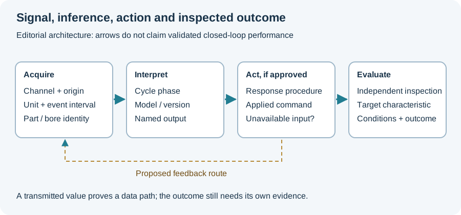
Our proposed cell record follows workpiece identity through loading, executed machining, process signals and inspection. A monitoring event can trigger an action without establishing the final bore geometry. A completed robot transfer can likewise be correct while a part still awaits its required observation.
Record what response was demonstrated. A reported classification result does not establish autonomous parameter adjustment, and the presence of a sensor does not establish a validated decision threshold. Those steps need their own evidence.
Evaluate the complete task boundary
For a proposed aerospace cell, identify the actual component and operation, concurrent events, sequential transfers and final acceptance stage. A supplier’s robot speed or spindle time covers only its stated boundary. Compare occupied time and accepted output before drawing a whole-cell productivity conclusion.
The monitoring-stage diagram below separates signals, decisions, action and observed outcomes. Use the RFQ worksheet to define the component, cell boundary and requested trial evidence. Continue to the automation overview for those evidence layers, or the AutoBohr report for what a named monitoring project actually reported.
Revision note
October 8, 2026: revised the technical explanation and connected reading after source review. Original publication date and URL retained.