BTA DrillingUpdated Oct 8, 2026
BTA Drill Head Selection: Brazed vs Indexable
Compare BTA head constructions through service workflow, diameter setting and a complete application cost record.
Editorial tool comparisonRead article
Understand BTA drilling external coolant supply, internal chip return, pressure-head interfaces and the reading route for a configured machine.
In UNISIG’s BTA machine explanation, cutting fluid enters around the tool and chips leave through the tool centre and drill tube. The German machine overview provides the corresponding terminology. The guide bushing locates the starting tool; the pressure head introduces fluid and contains it at the entry arrangement.
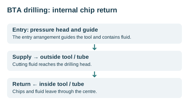
Editorial flow sketch based on UNISIG’s overview. Interfaces and proportions are schematic; this is not a sealing or installation drawing.
For an equipment enquiry, turn the diagram into an interface list rather than a list of headline capacities. The chosen head, tube connection, entry arrangement and workpiece belong to the same proposed configuration. Ask which drawing or product record identifies each connection. An omitted interface remains an open quotation item.
| Element | What to resolve | Further reading |
|---|---|---|
| Head and tube | Named construction and matching connection | BTA head construction comparison |
| Entry arrangement | Guide, workpiece contact and seal documentation | Pressure-head maintenance scope |
| Machine | Workpiece envelope, rotation arrangement and included options | BTA drilling machines |
These questions are editorial evaluation guidance. The source explains the mechanism; it does not certify an unlisted combination of parts or establish a pressure value for a new application.
The Alta Precision landing-gear case illustrates why maximum diameter alone is an incomplete purchasing comparison. UNISIG’s historical report describes an asymmetric part and a drop-bed configuration. Read the reported workpiece dimensions and machine arrangement together, then separate those facts from any unreported production result.
Prepare the actual part drawing, stock condition, trial quantity and required inspection in the drilling RFQ worksheet. When quotations arrive, keep recurring operation cost separate from setup and qualification. Use the same accepted-output boundary if you compare them in the cost worksheet.
The technical articles below expand the component and process questions. For a live malfunction, retain the actual observations in an incident record before attributing the symptom to the pressure head or chip return.
Choose your next step
Choose the question you are working on. These links organize the library; they are not machine operating instructions.
Start with the process
What Is BTA Drilling? The Single-Tube Circuit Explained →Prepare tools and setup
BTA Drilling Tools: Drill Heads, Inserts, and Guide Pads →Review parameters
BTA Drilling Parameters: Read the Tool-Specific Cell, Then Convert →Investigate problems
BTA Drilling Troubleshooting: Trace the Circuit and Incident →Compare BTA head constructions through service workflow, diameter setting and a complete application cost record.
Compare BTA and gun drilling with the same supplied part, delivery endpoint and accepted-output denominator, using an explicit hypothetical example.
Translate the three drilling circuit descriptions into an application enquiry with a specified component, tool train and inspection endpoint.
Understand the BTA drilling supply and chip-return paths, pressure head and tool train before comparing an installation for a particular bore.
How a radially movable cutting slide generates non-cylindrical internal contours in a deep bore, and why the long-chamber and short-chamber methods carry …
Distinguish named regrindable BTA heads from disposable or indexable constructions, then specify the returned assembly and inspection scope.
Compare BTA drilling machines by identified model, slide travel, coolant flow and pressure, then define a trial for the actual workpiece.
Identify solid-drilling, trepanning and finishing tools by the operation delivered, with a BTA assembly checklist.
Plan BTA installation verification around spindle, tube support, entry guidance and workpiece datums, with identified measurement references.
Identify the BTA pressure head and its cone or face-seal arrangement before interpreting leakage, selecting replacement parts or defining service …
Interpret the BTA cutting-edge and guide-pad CEL model, its validation differences and the gap between an offline simulation and an online twin.
Select a BTA drill tube by distinguishing hole diameter, tube OD and ID, then confirm the thread interface and documented inspection requirements.
Separate material-handling automation from demonstrated bore acceptance, and retain part identity across cell operations and inspection.
Separate a product-family quality claim from inspected bore size, datum-related geometry and texture over the required depth.
Connect chip discharge, cutting observations and bore inspection to one timed BTA incident record before identifying a cause.
Read BTA application claims through the incoming blank, required bore or contour and the proposed manufacturing route.
Calculate BTA batch cost from included charges and accepted holes, with a worked example separating cutting time from delivered output.
Evaluate a drilling service through offered operations, part-specific inspection evidence and a quotation with an explicit delivery boundary.
Distinguish chip removal, fine filtration and temperature control when reviewing the BTA return and supply circuit.
Read a scoped botek Type 12/64 speed/feed example and convert it to spindle and axial feed units without treating it as a universal recipe.
Trace the BTA coolant and chip circuit, then separate process identification from machine-specific commissioning.
Define tube-sheet drilling through hole identity, coordinate references, setup changes and an acceptance map that preserves exceptions.
Classify BTA drilling variations by the delivered operation, fluid route and identified tooling interfaces.
Read the cryogenic deep-hole project findings and distinguish small-diameter research from a demonstrated conversion of a conventional BTA circuit.