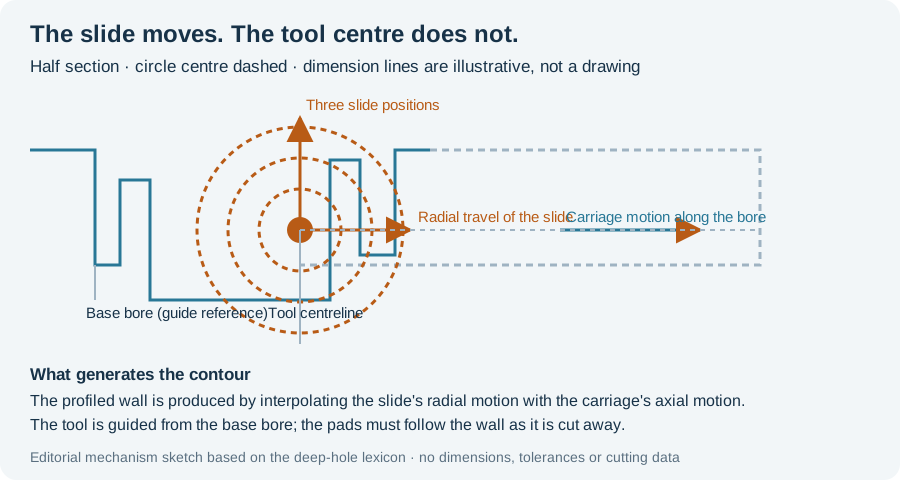
A deep bore does not have to stay cylindrical. Internal profiling — also written bottle boring, chamber boring, or in the German literature Auskammern — enlarges a guided bore into a rotationally symmetric contour that is not a constant diameter. It is a deep-hole operation, not a milling operation reached through a large opening, and the tool that performs it works from inside a bore that already exists.
The defining feature is a radially movable cutting slide
The German deep-hole lexicon is explicit about what separates this tool family from a drilling head. An Auskammerwerkzeug is used to produce Auskammerungen in deep bores; the tool concepts differ, but every one of them carries a radially movable cutting slide. That single sentence is the whole distinction. A solid drilling head, an enlarging head or a counterboring head cuts at a diameter fixed by its construction. A profiling tool changes its effective cutting radius during the cut.
Two consequences follow directly, and both shape what a shop can quote.
The first is control. BGTB states that profiling tools are normally operated through NC control so that the slide’s motion is interpolated with the motion of the boring carriage. The contour is therefore produced by the relationship between two axes, not by the tool’s shape alone. If either axis is unavailable, or if the interpolation is not the one the tool was set up for, the intended contour is not what comes out.
The second is where the drive sits. The slide’s actuation can be inside or outside the tool, depending on the tool concept and the tool size. That choice affects what the machine has to provide and how the tool is set up, so it belongs in the enquiry rather than in the assumption.
The lexicon gives a current application range for these tools of roughly Ø 40 mm to roughly Ø 900 mm, and notes specifically that its short-chamber design is usable from about Ø 40 mm to about Ø 300 mm. Treat those as one source’s stated envelope for a particular tool range, not as a boundary of the process.
One contour, two methods
The industry lexicon separates two ways of arriving at the same profiled contour. They are not competing tool purchases so much as two different answers to the question of how many cutting passes the contour needs.
| Long-chamber method (Langkammerverfahren) | Short-chamber method (Kurzkammerverfahren) | |
|---|---|---|
| Profile produced | The profiled internal contour over its whole length in one cut | A contour built from individual cuts |
| Where the tool is guided from | The already-machined guide bore, once the first cutting step is complete | The guide bore (base bore), for every individual cut |
| Guide pads | Must be radially adjustable, because after the first step the guide bore has been machined away | No extendable guide pads required |
| Complexity driver | Once a cut split becomes necessary, the tool needs more than one movable (controllable) guide pad alongside the movable cutting edge | The cut split is chosen so that each single cut can start from the safe guidance of the base bore |
The row distinctions follow BGTB’s entries for the two methods. The “complexity” column restates the cause that entry gives, not a cost ranking.
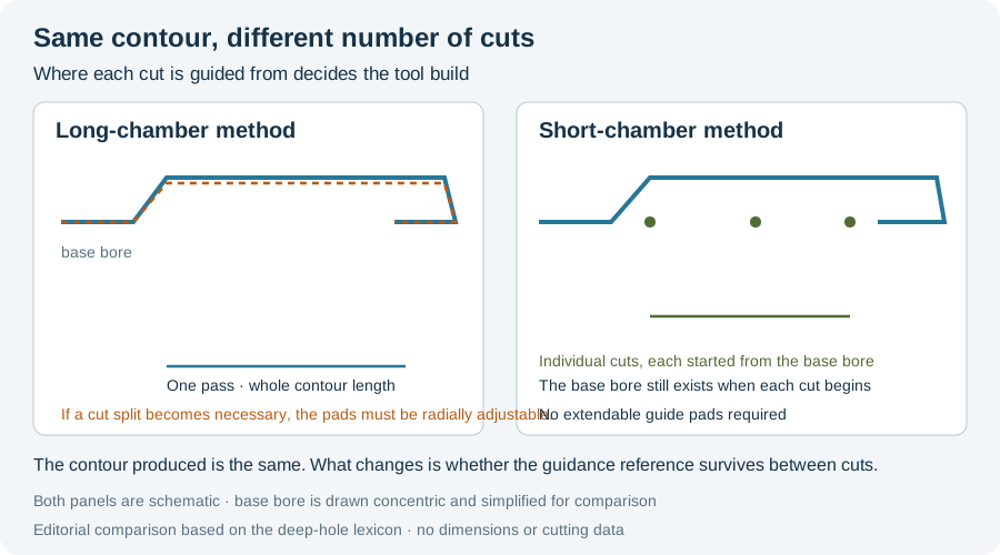
The short-chamber method is patent-designated as the “BGTB-Auskammerverfahren”. Its design logic is worth reading carefully, because it inverts the obvious approach: rather than making the tool sophisticated enough to follow a long contour in one pass, it chooses the cutting sequence so that every individual cut can be made from the safe guidance of the base bore. Guidance, not contour complexity, is the constraint being managed.
The long-chamber method is the more capable and the more demanding of the two. BGTB notes that all profiling tools — including those suited to the short-chamber method — can work in the long-chamber method as long as no radial cut splitting is necessary. As soon as splitting is necessary, the build and the operation become complex: the tool must carry more than one movable, controllable guide pad in addition to the moving cutting edge.
What a machining enquiry has to state
A profiling operation cannot be quoted from a diameter and a depth. The engineering description above implies the questions that decide feasibility:
- The finished contour, with its length. A chamber, a bottle shape, a conical section and a stepped contour are different outputs. A drawing that gives only a maximum diameter omits the length over which that diameter is held.
- Whether undercuts exist. The encyclopaedia description of internal profiling separates contours without undercuts — centrifugal casting moulds or conical bores in extruder cylinders — from contours with undercuts, such as propeller shafts or landing gears. An undercut changes the tool’s required reach.
- The incoming bore and how it was made. Profiling works from a pre-machined guide bore of adequate quality. Both the long- and short-chamber methods name that bore as the guidance reference. Its diameter, straightness and surface are inputs to the profiling operation, not incidental history.
- Whether a single cut is acceptable. This is what selects between the two methods, and it is a tool-and-machine question rather than a preference.
- The machine axes available for interpolation. The slide motion has to interpolate with the carriage motion. Confirm the machine actually provides what the chosen tool concept needs.
An important boundary belongs with that list. The English-language description of internal profiling also sets out a long-chamber variant in which guide pads must be hydraulically adjustable, and a short-chamber variant that needs no extendable pads because the tool is seated only in the pre-drilled guide hole. Those descriptions are attributed to the encyclopaedia entry, which in turn cites the lexicon tradition. This page does not claim that any specific machine, control or tool model supports a given contour. Where a job depends on the achievable profile tolerance, the roundness of the chamber or the surface left on the profiled wall, those have to come from a tool supplier’s documented envelope and from a trial on the actual part.
Reading the result
Because the contour is generated by interpolation rather than by tool form, the inspection plan has to be written against the contour and not against a diameter. A single-micrometer reading at one station cannot describe a chamber. The relevant characteristics are the profile positions along the bore, the diameter at those positions, the roundness of the profiled section, and the transition where the profiled region meets the guide bore.
Use the bore quality acceptance worksheet to attach each of those characteristics to a measurement method and a coverage statement before the first part is cut. For the underlying fluid and chip route, read What Is BTA Drilling? and BTA Drilling Tools.
Sources and limits
- BGTB GmbH, Dortmund — Tiefbohr-Lexikon. Auskammerwerkzeug (radially movable cutting slide, NC interpolation, drive inside or outside the tool, stated range about Ø 40–900 mm, short-chamber build about Ø 40–300 mm); Langkammerverfahren (profiled contour over the whole length in one cut; radial cut splitting forces movable guide pads); Kurzkammerverfahren (cut split chosen so each single cut starts from the safe guidance of the base bore). Read 11 October 2026. The lexicon states it makes no claim to completeness or correctness.
- Encyclopaedic process description of internal profiling (contours with and without undercuts; long-chamber and short-chamber variants; hydraulically adjustable guide pads) — consulted as a secondary description, 11 October 2026. It restates material cited to the German deep-hole literature rather than reproducing a primary standard.
- What this page does not assert. The lexicon describes tool concepts and their principles. It publishes no achievable profile tolerance, roundness value or surface parameter for a profiled chamber, and no cutting data or tool designation is given here either. Those belong to a tool supplier’s documented envelope and to a trial on the actual part.