A BTA drilling machine proposal needs to describe the configured machine, not just its maximum drilling diameter. The published specifications can narrow a shortlist, but the proposed workpiece, fixture, tool assembly and acceptance trial still determine what the purchase must demonstrate.
Compare rows belonging to the same model
DeHoff’s BTA/STS product page gives the following specifications for two identified models:
| Published item | BTA/STS 20 | BTA/STS 30 |
|---|---|---|
| Drilling capacity | 2 in / 50.8 mm | 3 in / 76.2 mm |
| Slide travel | 36, 60, 84 or 120 in | 120 in |
| Coolant flow | 60 gpm / 227 L/min | 120 gpm / 454 L/min |
| Coolant pressure | 500 psi / 34.5 bar | 500 psi / 34.5 bar |
The pressure entries are equal while the stated flows differ. This is a concrete reason to read both quantities rather than compare machines by pressure alone. The rows reproduce vendor specifications, not this site’s measurements of simultaneous delivered flow and pressure on a drilling job.
Travel is one dimension of the proposal
Ask the supplier to show the actual workpiece and tool arrangement on the machine layout. A slide-travel figure alone does not establish the maximum delivered bore depth: the proposal also needs to account for the entry arrangement, tool assembly, workholding and available motion in that configuration.
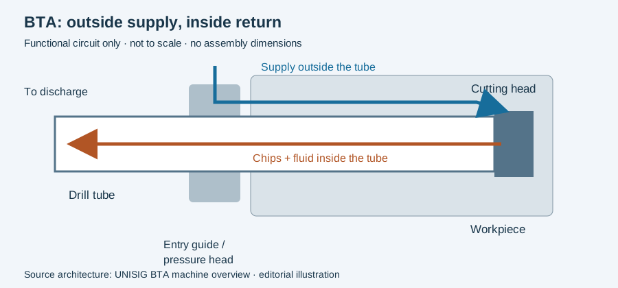
UNISIG’s machine overview explains that BTA coolant travels outside the tool and chips return through the tool, tube and spindle. Its German counterpart confirms the same route. Include that return system and its peripheral equipment in the proposed installation rather than treating the drilling spindle as the complete purchase.
Define what acceptance will show
Use an identified representative part, tooling and inspection plan for the application trial. State which bore characteristics, output and operating conditions the trial will record. A catalog range cannot substitute for that report, and this two-model example is not a ranking of manufacturers.
Continue to installation and alignment acceptance for commissioning records, or BTA automation when handling and inspection are included in the cell.
A machine envelope is only one part of the arrangement
The circuit sketch identifies entry guidance, external delivery, the tool train and internal exhaust. Compare that functional arrangement with the actual layout proposed for the component. Nominal travel alone cannot show where the blank is held, how the entry is approached or where the finished part is inspected.
An illustrative comparison could contain two machines with sufficient listed travel but different loading and support arrangements. The useful next step is a layout for the same blank, datum scheme and delivery route. A quoted maximum bore length and a component drawing use different boundaries unless the provider explains their relationship.
Keep spindle demand, fluid delivery and tool support as distinct parts of that review. A calculated cutting-demand estimate does not account for every machine subsystem. Likewise, an available pump specification does not document operating delivery at the tool for the proposed assembly.
Move from the layout to tube/connection selection and the installation relationships. The RFQ worksheet collects the component and delivery requirements so the comparison can use one defined task.
Revision note
October 8, 2026: revised the technical explanation and connected reading after source review. Original publication date and URL retained.