Follow the fluid circuit
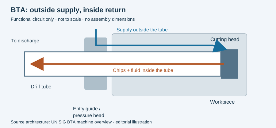
UNISIG describes coolant entering the space outside the BTA tool and chips returning through the tool centre and spindle. Its machine overview identifies a pressure head sealing around the tool and guide bushing. These are manufacturer descriptions of the process architecture. Tooling · Machine components.
A useful assembly review follows the complete loop: supply connection, pressure head, cutting zone, head opening, tube and discharge. Mark each interface on the proposed machine drawing. This makes a missing return connection visible before a discussion becomes limited to pump pressure.
What each interface needs to establish
| Interface | Question for the actual installation | Evidence to retain |
|---|---|---|
| Workpiece entry | Which component locates the tool and seals the entry? | Bushing and workholding drawing |
| Supply | Where are pressure and flow measured? | Sensor locations and loaded readings |
| Head and tube | Are the connection and chip passage compatible? | Named head, tube and connection specification |
| Return | Where do fluid and chips leave the spindle? | Discharge and filtration layout |
| Long tool support | Which supports move during the stroke? | Support positions and approved setup |
These questions are our editorial commissioning framework. They are not operating instructions or measured acceptance limits.
Diagnose the circuit rather than a single number
For an incident record, preserve the operating depth, time, pressure-measurement location, flow record if available, tool identity and observed discharge. A pressure reading without its location cannot be compared meaningfully with another machine’s specification. State which observations are missing before selecting a cause.
Do not adopt a catalogue’s speed advantage as the result of this installation. Compare acceptable completed holes and total machine time in a controlled application trial. Use the incident worksheet to keep observations together and the RFQ worksheet to request the assembly details.
Follow one loop through the installation
Read the diagram below from the supply side to the cutting zone, then return through the head and tube to the discharge. The arrows represent functions, not a dimensional machine drawing. The entry-side supply and central exhaust must both appear in the installation record.
A useful troubleshooting distinction is between where chips are generated and where they are observed. If discharge changes at the spindle, the observation does not automatically locate a restriction at the head. The intervening passage and the available time-aligned measurements remain part of the question.
For example, an illustrative log containing an outlet observation and a pump reading taken after the machine stopped cannot reconstruct delivery while cutting. Preserve operating depth and state with the readings. This is a record-design example; it does not prescribe a pressure, flow or restart sequence.
Continue from the circuit to the tube and connection specification. If the actual task is a delivery fault, the coolant investigation explains why different sensor locations and operating states cannot be treated as one paired measurement.
Revision note
October 8, 2026: revised the technical explanation and connected reading after source review. Original publication date and URL retained.