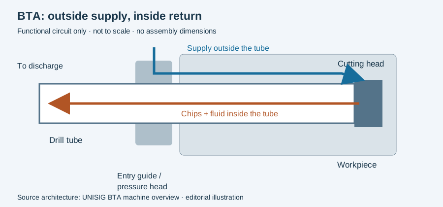
BTA pressure head maintenance depends on the BOZA arrangement actually installed. UNISIG’s German machine overview describes the BOZA as sealing the tube and guide-bushing assembly while introducing coolant outside the tool. That function does not imply that every BOZA uses the same workpiece interface.
Cone and face arrangements are different constructions
The 2017 BTA-Tiefbohrsysteme equipment catalog documents these examples:
| Historical model | Documented workpiece interface |
|---|---|
| Type 2210, printed page 6 | Non-rotating clamping cone for holding, centering and sealing |
| Type 2220, printed page 8 | Non-rotating face seal; a flat entry face is specified |
| Type 2270, printed page 12 | Rotating face seal pressed by coolant pressure; a flat entry face is specified |
The catalog also identifies replacement components restricted to particular types. Use these descriptions to understand why a head identity matters; they are historical construction examples, not confirmation that a replacement part is currently available or interchangeable.
Describe the leaking interface before naming the fault
Record whether the observed escape is at the workpiece face, tube-side connection or a housing connection, along with the installed head and cycle stage. Keep photographs attached to those locations. “BOZA leaking” is too broad to tell a service technician which interface needs assessment.
Compare the workpiece preparation and fitted components with the applicable head documentation. If leakage appears after a part or component change, retain that change as part of the event sequence. Its timing is evidence to investigate, not proof of a unique cause.
Specify service against the identified assembly
Use the maker’s current instructions for isolation, dismantling, seal compatibility, replacement and return-to-service checks. Neither cited overview provides a universal seal material, inspection interval or rejection clearance, and the historical catalog is not a maintenance manual.
Attach the replacement references and returned configuration to the machine acceptance record. Keep the fluid observations with the coolant circuit so a later investigation can distinguish a component change from a supply-system change.
Identify the interface before explaining a leak
The machine overview places the pressure head around the tool and entry guide to introduce external coolant. In an incident, identify which installed interface showed the observed loss. “The seal failed” is already a proposed explanation if no finding identifies the component and condition.
An illustrative record might note fluid appearing at a named entry interface during one operating state. Keep its location, state and time with the setup identity. It does not determine whether the explanation concerns the sealing element, installation relationship, operating condition or another interface. Record authorized inspection findings in their own field.
Maintenance and acceptance also have different endpoints. A changed sealing element and a recovered display reading document particular interventions and observations. They do not independently establish the quality of bores produced before or after the event. Retain the relevant inspection disposition with the recovery record.
Replacement dimensions, materials, tightening and restart instructions come from the actual provider’s controlled documentation. The circuit diagram below helps locate functions; it is not a disassembly procedure. Continue to coolant troubleshooting for measurement comparisons and installation alignment for the setup relationship.
Revision note
October 8, 2026: revised the technical explanation and connected reading after source review. Original publication date and URL retained.