Multi-axis CAM drilling first needs an explicit set of holes and orientations. A clean-looking operation can be incomplete if collision handling skips a location or trims a motion. Review what CAM calculated as well as what the final program contains.
Orientation starts from a reference
The Fusion drilling reference says the setup WCS Z direction provides the default tool orientation, which the Tool Orientation settings can override. It separately describes four- and five-axis machining settings. These are documented operation controls; they do not prove that a particular machine can reach every selected axis.
Retain the intended bore vector in part coordinates and the orientation used for the operation. Include the entry surface and target depth. An angled access move and the subsequent drilling interval are different parts of the review.
Collision handling can change the result
The same Fusion reference describes shaft/holder inclusion, collision abort, trimming and skipping colliding holes. It states that trimming is unavailable for some cycle types, including guided deep drilling. It also describes chained operations with progressively longer tools for remaining holes.
These settings make the selected tool assembly important. If a calculation omits a colliding hole, compare the generated location list with the required drawing locations. If it finds a longer tool projection, reconcile that proposal with the physically installed assembly and the applicable tool procedure. A toolpath log is useful evidence of what changed; it is not a bore measurement.
Review links and the cut separately
After establishing the reachable locations, inspect inter-hole movement with the fixture, holder and relevant machine geometry. Then review the entry/cutting/withdrawal sequence at each orientation. Fusion’s cycle reference makes the posted representation dependent on the controller and postprocessor, so an accepted orientation does not settle the cycle semantics.
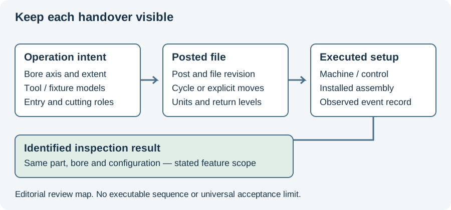
This page concerns the CAM calculation and its exclusions. The five-axis programming article below follows the coordinate handover into machine execution. Keep both tied to the same assembly and emitted program revision.
The incident worksheet can record a missing location or unexpected transition alongside the original CAM settings. Use the program-evidence diagram to locate the failed handover before changing an unrelated drilling parameter.
Revision note
October 8, 2026: revised the technical explanation and connected reading after source review. Original publication date and URL retained.