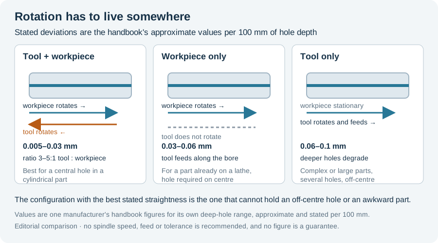
Three configurations appear in deep hole drilling, and machine builders sell all three: the tool rotates, the workpiece rotates, or both rotate in opposite directions. The choice is not a preference. It decides which parts can be held at all and what straightness the process is capable of, so it belongs at the top of a machine enquiry rather than in the specification appendix.
The configuration is declared as three options
ISCAR’s deep hole drilling handbook states the distinction in the plainest terms available: rotational motion can be produced by the part, by the tool, or by both, while linear movement is usually performed by the tool — and the combination depends on the geometry and size of the workpiece as well as on the available equipment.
That sentence contains the whole decision structure. Rotation has to live somewhere; the part’s geometry and size decide where it can be, and the machine decides what is available. Everything else is consequence.
What the handbook gives each configuration
The same source tabulates the three options with an approximate deviation from straightness for each. These are the handbook’s own figures and they are stated per 100 mm of hole depth:
| Configuration | Stated deviation from straightness | Where the handbook places it |
|---|---|---|
| Rotating tool and workpiece (opposite directions) | 0.005–0.03 mm per 100 mm | Best suited to a hole in the centre of a cylindrical part. Less suitable if the hole is not central, or if the part is hard to revolve because of its geometry or size |
| Rotating workpiece, non-rotating tool | 0.03–0.06 mm per 100 mm | Useful when the part is machined on a lathe or turning station and the hole is required in the centre of the workpiece |
| Rotating tool, stationary workpiece | 0.06–0.1 mm per 100 mm | Relatively good straightness in shallow holes, deteriorating significantly as the hole gets deeper. Suited to complex or large workpieces, to several parallel holes, or to a hole that is not central |
One manufacturer’s handbook figures for its own deep-hole range. They are approximate, stated per 100 mm of hole depth, and they describe capability at the level of configuration — not a tolerance any given machine will hold.
Read the three rows together and the trade-off is explicit rather than implied. The configuration with the best stated straightness is the one that cannot hold a non-central hole or an awkward part. The configuration that handles the awkward part is the one whose straightness is stated to degrade as depth increases.
Counter-rotation carries a ratio, not just a direction
Where both elements rotate, the handbook adds a second specification: the recommended rotation ratio of tool to workpiece is 3–5:1 — for each revolution of the workpiece, the tool makes three to five revolutions.
That is a design parameter. It determines what the spindle and headstock drives have to deliver as a pair, and it means a counter-rotation machine cannot be assessed from either spindle speed alone. A machine offered with a very fast tool spindle and a very slow workpiece spindle is not automatically at the ratio; the enquiry has to state it.
The arithmetic of combining two opposing speeds — and the difference between relative speed and evidence of an improved bore — is handled separately in Counter-Rotation in Gun Drilling. This page is about choosing the configuration, not about computing what it produces.
The configuration sets what you can hold
The decisive constraint is often workholding rather than straightness, because a part that must rotate is limited to parts that can be rotated — and rotated true.
Mollart’s Omnisprint series, sold in North America through Bourn & Koch, is documented as a three-axis machine whose three-axis capability “allows for drilling of multiple off-center holes in one clamping”, with an optional rotating fixture so that blind holes can be drilled on both ends of a workpiece. The same machine is offered with up to six spindles, and the two-spindle LD2-750 is configured to drill two workpieces at once.
Manufacturer product description, retained as attribution.
Two things follow. First, off-centre work and multi-hole patterns are a stated capability of a rotating-tool configuration — the workpiece stays put, so there is no balance problem and no geometry that has to be revolved. Second, the rotating-workpiece configuration is the one that requires the part to be suitable for rotation at all; a long shaft with an unbalanced feature is not interchangeable with a balanced one on such a machine.
A commercial configuration example
Manufacturers do sell the counter-rotation arrangement as a named feature, which is a useful check that the handbook’s first row is not theoretical. A horizontal single-spindle gun drilling machine offered by Dezhou Guanlu describes its cutting mode as the workpiece rotating clockwise while the gun drill spindle rotates counter-clockwise, and presents the arrangement as reducing cutting vibration and improving hole straightness.
The same page is candid about the penalty. It states its own straightness deviation as a figure per 500 mm for a rotating workpiece and a larger figure per 500 mm for a fixed workpiece — the same ordering, and the same reason, as the handbook table.
Manufacturer’s own product description. The specific deviation values are not reproduced here because a supplier’s figure applies to that machine’s configuration and cannot be transferred to another; the quoted arrangement is what this page uses it for.
What the enquiry has to state
A configuration question cannot be answered from a drawing alone. These are the inputs that decide it:
- Hole position. Central or off-centre. A non-central hole on a rotating-workpiece machine is the case both sources single out as unsuitable.
- Part geometry and mass. Whether it can be rotated true, and whether the machine’s headstock and steady arrangement can carry it.
- Depth-to-diameter ratio. Because the rotating-tool figure is the one stated to degrade with depth, the deeper the hole the more the configuration matters.
- The straightness the bore must hold, and over what length. The handbook figures are per 100 mm; a requirement written over the full bore length has to be converted before it can be compared.
- Whether more than one hole is drilled per clamping. Multi-hole and multi-spindle work point one way; a single central bore in a turned part points the other.
- The rotation ratio, if both rotate. Ask for it as a number, not as a feature name.
Take those answers to the machine comparison. For the wider question of whether an existing machining centre can carry the work at all, see Deep Hole Drilling on an Existing CNC; for how the tool is held and what runout that adds, see Deep Hole Drilling Tool Holders.
Sources and limits
- ISCAR, Drilling Handbook, Deep Hole Drilling section, Deep Hole Methods. Read 11 October 2026. Source of the three configurations, the 3–5:1 ratio, and the straightness figures; manufacturer application guidance for its own deep-hole range.
- Bourn & Koch / Mollart Omnisprint LD2-750, product page. Read 11 October 2026. Source of the three-axis off-centre and rotating-fixture statements and the spindle counts; manufacturer product description.
- Dezhou Guanlu, industrial CNC gun drilling equipment. Read 11 October 2026. Source of the named counter-rotation configuration; manufacturer product description, quoted as an arrangement rather than as verified performance.
- German-language sources. No German-language source was established for this comparison, so no German term is asserted and the straightness figures are reported as that handbook’s alone.
- Not asserted. No spindle speed, feed, coolant pressure or tolerance is recommended here, and none of the cited straightness figures is presented as a guarantee. A configuration’s stated capability and a specific machine’s acceptance test are different things.