The CFRP-shaft gun drill in dynoSpan is a proposed tool structure. CFRP identifies the shaft material, rather than the workpiece being drilled. The IFW/ISF announcement, published April 23, 2026 in English and German, describes a joint research concept with several interacting components.
A tube replaces the metallic shaft
The concept substitutes a CFRP tube for the metal shaft and uses its laminate construction as part of the damping design. The announcement presents reduced unwanted vibration, improved hole quality and reduced wear as intended benefits. It does not publish a matched production series establishing those gains.
This makes the assembled tool the appropriate object of comparison. A shaft-material name cannot isolate the contributions of the laminate, joint, head and support arrangement.
The metal-to-composite joint belongs to the concept
The source describes planned layered hybridization at the interface, with metallic load-transmission elements joining the head to the laminate. An additively manufactured head and modular replacement of components are also part of the research description.
These details explain why evaluating only a loose CFRP tube would answer a different question from evaluating the complete drill. The joint transmits the tool’s loads, while the chosen head and assembly determine what is actually being compared.
A modular comparison needs a configuration history
Our editorial interpretation is to record a tool configuration at each trial interval. Identify which components were installed and which were changed. If a head replacement coincides with another joint or shaft construction, the comparison has changed more than one variable.
That can be a useful engineering trial, but the conclusion should describe the complete configuration rather than assigning the result solely to “CFRP.” The same reasoning applies when service changes a conventional gun drill’s head geometry.
Measure the claimed response directly
A vibration signal, a wear image and a finished-bore characteristic are complementary observations. If the proposed benefit is lower vibration, specify the sensor and observed interval. If the benefit is accepted output, retain the relevant bore measurements and inspection coverage. A signal reduction alone does not report the drawing characteristic.
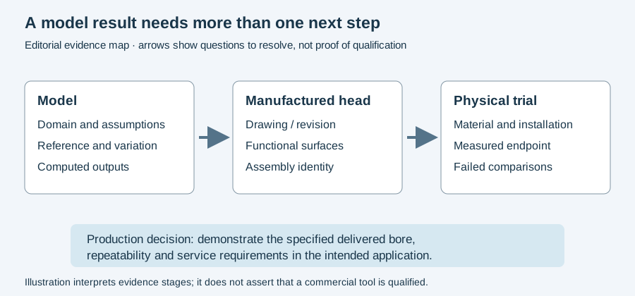
The model-to-trial figure below shows the evidence needed between a design proposal and an application decision. For a future documented case, the case-submission form captures the baseline, configuration and result, with attribution agreed separately. It does not imply that the announcement already contains a production case.
Continue to the dated dynoSpan report for the announcement’s chronology, or gun-drilling vibration for the distinction between an observed signal and a diagnosed cause. This page’s task is to explain the proposed structure so later results can be read against the right assembly.
Revision note
October 8, 2026: revised the technical explanation and connected reading after source review. Original publication date and URL retained.