Deep hole drilling equipment selection joins several interfaces: tool to spindle, fluid supply to tool, entry guidance to workpiece and program to executed operation. A machine’s nominal diameter capacity leaves those interfaces unspecified.
Start with the selected fluid circuit
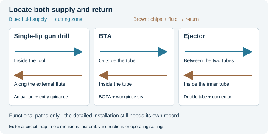
The botek mechanical-process descriptions separate single-lip, BTA and ejector supply and return paths. BTA includes an oil-supply apparatus and workpiece seal; ejector uses a connection piece with a double-tube arrangement.
This gives a practical starting point for an equipment review. Trace the complete path from supply to cutting zone and return collection. Identify the actual component at each interface rather than assuming that a pump rating completes the installation.
The entry apparatus performs more than one function
The BOZA description identifies supply to the annulus, sealing and entry guidance, with different versions for rotating and nonrotating workpieces. The chosen workpiece arrangement therefore matters to the apparatus description.
A proposal should show which assembly is fitted to the machine and how the workpiece starts the operation. The manufacturer page provides functional detail, but no generic clearance or setting suitable for every installation.
Keep space and sequence in the same review
Our editorial equipment framework records the incoming workpiece, tool assembly and executed travel. Loading, entry, cutting and withdrawal are different stages. A tool that reaches the required drilling length can still leave the surrounding installation unresolved if the proposal describes only the cutting stage.
Similarly, retain the control and program configuration. A CAM operation and a posted program are separate records; the executed setup adds offsets, workholding and the actual tool. The linked CNC reading develops that handover.
Measure delivery at the actual tool state
Supply settings and installed-tool observations need a measurement point and operating state. If the proposal quotes pressure or flow, state where it is measured and whether the tool is stationary or cutting. A number detached from its state cannot describe the complete chip-transport path.
The coolant-system reading follows that distinction. It also keeps treatment and clean supply separate from a nominal pump specification.
Acceptance closes the equipment comparison
Define the required bore characteristics and how the proposed installation will be evaluated. A machine reaching the endpoint and a bore satisfying the drawing are separate outcomes. Include any later finishing actually needed for the delivered feature.
The circuit figure explains the functional interfaces. Use the RFQ worksheet to record the common drawing and proposed equipment scope, then continue to coolant systems for delivery evidence or CAM programming for the posted-file and executed-setup distinction. These connections make equipment selection a reviewable route instead of a purchase decision based on one capacity number.
Revision note
October 8, 2026: revised the technical explanation and connected reading after source review. Original publication date and URL retained.