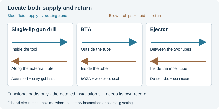
A deep hole drilling method comparison should first identify the fluid and chip circuit. Gun drilling, BTA and ejector drilling have different paths through the tool and installation. A nominal diameter does not describe those interfaces.
Three circuits in the original description
The German botek process page provides the following distinctions:
| Method | Fluid supply | Chip and fluid return | Interface identified by the source |
|---|---|---|---|
| Single-lip gun drilling | Inside the tool | External flute | Suitable supply and guidance arrangement |
| BTA | Outside the tube, along the bore | Inside the tube | BOZA and workpiece seal |
| Ejector | Between outer and inner tubes | Inside the inner tube | Ejector connection piece |
The source describes ejector drilling without a workpiece seal. That feature changes one interface; it does not by itself qualify an arbitrary machining-center installation.
Locate the equipment that completes the path
BTA-Tiefbohrsysteme’s BOZA description identifies fluid delivery, sealing and the guide-bush carrier at the entry. The tool, supply apparatus and workpiece therefore belong in one equipment description.
For an ejector proposal, the double-tube assembly and connector need corresponding identification. For gun drilling, retain the actual tool and entry guidance. The schematic below shows functional paths rather than detailed assembly instructions.
A circuit is not a universal capability envelope
UNISIG’s technical reference explicitly describes tooling ranges as generalized and dependent on the tooling manufacturer. A family-level diameter or depth range should keep that qualification. It is not a physical exclusion rule for every competing process.
The original table also does not create a production ranking for the reader’s steel, geometry and acceptance requirements. If a complete route differs in finishing or inspection, its cycle represents a different delivered stage.
Compare the actual required output
Our editorial comparison records incoming geometry, material condition, tool assembly, machine interface and final characteristic. Those fields explain what is being proposed before a performance claim is evaluated.
If one candidate is installed on existing equipment, include the connector, guidance and supply changes it actually requires. If another is a dedicated machine, describe its complete workpiece arrangement. “Retrofit” and “dedicated” are route choices, rather than automatic cost or quality outcomes.
Use the RFQ worksheet to retain the same drawing and inspection scope across proposals. Continue to equipment selection for the interfaces, or full-route cost comparison for the accounting boundary. The circuit figure helps the reader understand why a suitable tool diameter is only one part of a usable installation.
Revision note
October 8, 2026: revised the technical explanation and connected reading after source review. Original publication date and URL retained.