Deep hole drilling method selection
This is a decision guide. It helps build a supplier shortlist from a drawing; it does not calculate or certify a machining solution.
Prepare the hole specification
Record diameter limits, full depth, through or blind condition, bottom shape, intersecting holes, entry/exit geometry, material grade and heat treatment. Add datum-based position and straightness requirements, surface texture, inspection access, lot size and annual demand.
Calculate L/D from the specified depth and diameter. Keep the actual dimensions alongside the ratio: two holes with the same ratio can need very different systems.
Build a mechanical-method shortlist
| Requirement | Options to investigate | Evidence to request |
|---|---|---|
| A small, long precision bore | Gun drilling and a suitable specialist spiral-fluted drill | Tool rating, pilot procedure, coolant demand and comparable parts |
| A bore that fits BTA tooling | BTA, with gun drilling or ejector where appropriate | Head/tube availability, pressure head and machine capability |
| Installation on an existing machine | Gun drilling, specialist spiral drill or ejector attachment as applicable | Travel, support, connector, coolant and control integration |
| Large solid-stock removal | BTA or trepanning | Power/torque, core handling, workpiece support and finishing |
| A geometry or material unsuitable for the mechanical shortlist | EDM, ECM or laser where technically applicable | Material compatibility, aspect ratio, surface integrity and trials |
The method capability reference gives attributed examples. Diameter and depth are screening inputs, not universal cutoffs. Confirm the exact tooling configuration instead of imposing a fixed method-wide limit.
Check quality before choosing equipment
Resolve size limits using the basic dimension and the specified tolerance class. Define geometry and texture independently. Ask how the finished hole will be measured, including at depth. If an additional finishing operation is needed, compare the entire chain rather than as-drilled performance alone. See tolerances and surface texture.
Compare production routes
For each candidate, estimate setup and changeover, cut/return time, tool consumption, inspection, finishing and expected accepted output. Decide between existing equipment, dedicated equipment and outsourcing using your demand and capacity; there is no universal annual-volume threshold.
Confirm by application review
Send the drawing and material condition to the tool supplier and machine builder or service provider. Request written capability conditions, a representative trial where needed, and agreed acceptance measurements. Use the RFQ guide to organize the request.
What the linked calculator actually calculates
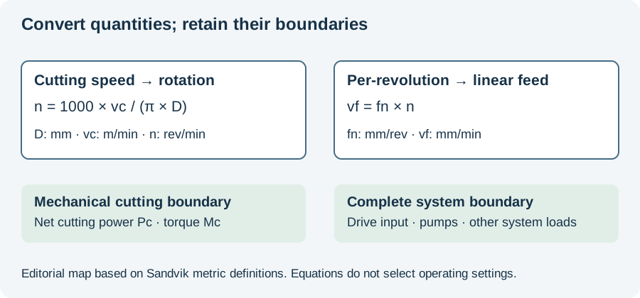
UNISIG’s technical reference separates selected cutting quantities from converted spindle and feed quantities. The site’s working speed/feed calculator performs those conversions. It does not use diameter or L/D to award a winning method.
The distinction matters when using a numerical result in the shortlist. An rpm value calculated from a selected speed and diameter is arithmetic, not evidence that the machine, tool or supply circuit suits the requested bore.
Retain the inputs when comparing proposals
Our suggested decision record keeps the required feature, candidate configuration, available evidence and unresolved question in separate fields. For example, an identified coolant-interface mismatch should remain visible instead of being hidden behind an overall suitability score.
The diagram below connects named cutting quantities and states their calculation boundary. Open the actual calculator when the unresolved task is a unit conversion. Continue to equipment selection for physical interfaces, or the method-selection workflow for screening routes before costing them.
Revision note
October 8, 2026: revised the technical explanation and connected reading after source review. Original publication date and URL retained.