Deep hole drilling methods can be organized by two different questions: what happens to the workpiece, and how the tool receives fluid and returns removed material. Keeping both questions visible is more useful than a list ranked by nominal depth.
Begin with the machining task
UNISIG’s technical reference distinguishes solid drilling, trepanning, counterboring, pull boring and subsequent operations. Solid drilling and trepanning begin from solid material. Enlargement begins from an existing bore. Finishing changes a feature that has already been produced.
These descriptions identify different starting tasks. If a process comparison ignores the incoming geometry, it can compare a solid-drilling cycle with an enlargement operation as though they remove the same material.
Then identify the supply and return architecture
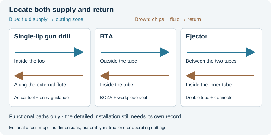
The German botek process explanation distinguishes internal supply and external flute return for single-lip drilling, external supply and internal return for BTA, and a double-tube arrangement for ejector drilling.
The circuit figure below shows those functional paths. It omits dimensions and detailed seals, so it explains the architecture without becoming an assembly drawing or an operating procedure.
The task and circuit describe different parts of the route
A tool can belong to a fluid-system family while performing a specific removal operation. “BTA” therefore does not tell the reader whether the proposal drills solid, retains a core or enlarges an existing bore. Identify the actual head and operation.
The trepanning reading develops the retained-core case; secondary operations explains enlargement and finishing. These pages answer different questions within one machining route instead of competing to be another general methods list.
Keep nontraditional routes identifiable
Electrode and optical processes need their own apparatus and access descriptions. They should be considered against the actual feature and material rather than assigned all the advantages of a generic nontraditional category. The dedicated ECM/EDM/laser article maps those removal mechanisms.
Turn the description into a comparable request
Our editorial workflow starts with the required bore and incoming stock, identifies a complete candidate route and locates its observation stages. Only then can processing time, tool consumption and accepted output be compared coherently.
The RFQ worksheet records the common drawing and scope for candidate proposals. It does not select a method from diameter alone. Use it when the next task is a documented comparison, and keep any later finishing within the same requested output.
Continue to the method comparison for the circuit and machine-interface differences, or method selection for screening incompatible routes before calculating cost. Together, the article, schematic and worksheet connect a process name to a defined machining task.
Revision note
October 8, 2026: revised the technical explanation and connected reading after source review. Original publication date and URL retained.