Through and blind deep holes need more than a nominal drilling depth. The drawing can specify a full-diameter passage, a bottom profile, an opening at the far face or an intersection with another feature. Those descriptions should remain identifiable when a machining route is proposed.
Name the depth convention
A depth to the tool’s furthest point and a depth over which the complete specified bore exists are different feature descriptions. Identify the drawing convention before discussing tool travel. This page provides no automatic CNC endpoint or generic point allowance: the actual tool and bottom geometry matter.
For a through feature, describe the required condition at the exit. For a blind feature, retain the bottom shape and any remaining material requirement. A single number labeled “depth” may leave those distinctions unresolved.
Bottom forming is a separate described operation
UNISIG’s technical reference, page 2, identifies specialized bottom-forming tools guided along the finished bore. It lists radius, step and flat-bottom profiles as examples. The source therefore distinguishes making the passage from delivering a particular base profile.
That distinction helps organize the route. If the proposed drill does not itself produce the specified bottom, identify the additional operation and its observation stage rather than treating the drawing requirement as an automatic drilling result.
Core recovery changes the blind-hole proposal
The same reference notes that trepanning may be impractical in blind-hole applications because the core is difficult to remove. A retained core is part of the process description, so its recovery must be considered with the remaining bottom geometry.
The trepanning reading develops that question using original English and German tool descriptions. It does not impose a blanket depth ratio or replace the actual tool-maker’s application review.
Inspection follows the completed feature
Our editorial inspection framework separates passage measurements from bottom or exit observations. State which characteristic is checked and where the observation is made. A local diameter measurement does not describe a shaped base, and a photograph of an exit does not evaluate the entire bore axis.
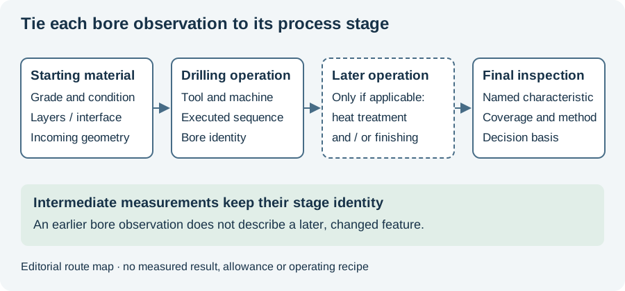
Retain intermediate observations if the route includes more than one operation. An as-drilled measurement can explain what entered the next stage; a final observation can assess the delivered feature. Both belong to the same bore identity.
The material-to-inspection diagram below shows those stage relationships. Use the quality worksheet to name the required feature and observation coverage. Continue to trepanning for the core-removal question or secondary operations for how enlargement and finishing change what should be measured. These links connect the depth convention to the actual route instead of leaving “through” and “blind” as simple labels.
Revision note
October 8, 2026: revised the technical explanation and connected reading after source review. Original publication date and URL retained.