Multi-spindle deep hole drilling parameter coordination depends on the installed architecture. A dual-spindle machine with dedicated pumps is a different delivery system from several tools supplied by a shared branch network. Spindle count alone does not identify how pressure, flow or motion are controlled.
A named dedicated-pump example
UNISIG’s 2022 surgical-instrument manufacturing account describes the UNE6-2i-750-CR with two independent drilling spindles and dedicated coolant pumps for each spindle. The manufacturer also discusses handling, clamping and sequencing as parts of the integrated operation.
Its German machine finder distinguishes named dual- and multi-spindle models. The listing does not establish that every model shares the dedicated-pump architecture of the reported surgical system.
This is a manufacturer description, not an independently measured throughput comparison. Do not derive a universal feed reduction or output multiplier from it.
Identify which combination was measured
For a shared supply, record the active outlets when acquiring a branch observation. One tool active, both tools cutting and one tool entering are different operating combinations. A common pressure display does not by itself give each tool’s flow.
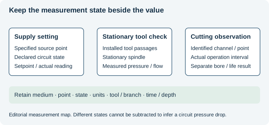
Gühring’s actual-tool stationary measurement description helps define a separate check: the installed tool and stationary spindle belong to that measurement. If the job uses multiple branches, preserve their configuration rather than treating the check as an in-cut result for all tools.
Compare arithmetic demand with real delivery
For an explicitly assumed example, two branches each assigned a target of 8 L/min sum to 16 L/min. That arithmetic neither predicts the flow obtained at each tool nor selects pump pressure. Use the actual circuit and operating observations to assess delivery.
Likewise, two independent cutting operations do not imply twice the accepted production output. Handling, sequencing, tool-service intervals and inspection may occupy different portions of the route.
Keep each bore tied to its spindle
Retain branch/spindle identity, installed tool, service interval and part/bore identity with the measured result. If one bore fails while the other passes, that mapping prevents a combined machine record from concealing the difference.
The measurement-state diagram below highlights the state and point that belong beside a delivery value. Use the incident worksheet for an unexpected change. Continue to coolant optimization for the pressure/flow question, or CNC handover when the problem concerns coordinated motions and executed settings.
Revision note
October 8, 2026: revised the technical explanation and connected reading after source review. Original publication date and URL retained.