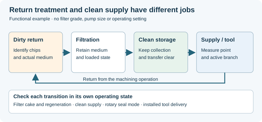
A deep hole drilling coolant system is easier to assess by following the fluid than by reading a list of components. Return treatment, clean storage, pressurized supply and the rotating interface have different jobs. The tool’s internal passages and chip-return route complete that circuit.
Start at dirty return
KNOLL’s KF circuit describes dirty fluid entering filtration, collection in a clean tank and subsequent supply by pumps. Its media-regeneration sequence belongs to the return-treatment stage. This is a named circuit architecture, not a requirement that every installation use a belt filter.
Use the drawing of the actual machine to identify where chips separate from liquid and how liquid transfers between tanks. A transfer pump and a tool-supply pump can occupy different positions and see different media conditions. Their labels should retain those functions.
Find the rotating boundary
Where supply passes into a rotating spindle, a rotary union provides another defined interface. Deublin’s coolant series distinguishes sealing arrangements for fluid, dry-air and MQL operation, as well as mounting and stroke requirements. The selected union’s operating states belong to its own specification.
This matters when comparing an external supply package with a machine’s internal delivery path. A suitable pump alone does not define whether the spindle interface, holder and tool passages match the intended medium and sequence.
Continue through the actual tool
The botek single-flute catalogue describes gun-drilling supply through the tool and chip-laden return along the external flute. The BTA catalogue describes another tool system; the BTA circuit map in the method article locates supply outside the drill tube and return inside it.
Do not draw all deep-hole methods as one through-spindle arrangement. Match the functional diagram to the selected method before assigning a component or measurement point.
Put units and operating state beside the observation
Pump setting, line pressure, installed-tool flow and return condition need their own names. Record point, units, medium, tool or branch and whether the spindle is stationary or cutting. Two values acquired in different states do not automatically describe a pressure loss across one component.
For an existing installation, that mapping can be made before changing settings. It helps the investigation distinguish a documented circuit relationship from an assumed cause.
The loop figure below locates return and supply functions. Use the RFQ worksheet to retain interfaces and exclusions for a proposed integration. Continue to rotary unions for seal-state selection, or coolant measurement for the relationship between setting, stationary check and cutting observation.
Revision note
October 8, 2026: revised the technical explanation and connected reading after source review. Original publication date and URL retained.