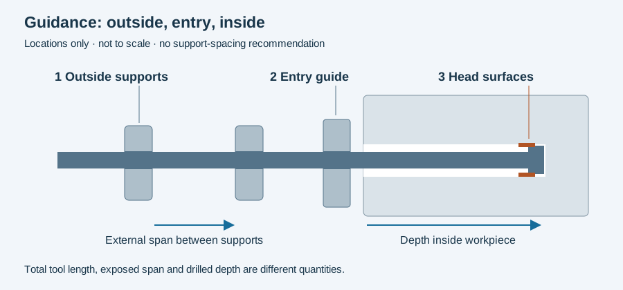
Guide bushings and workholding meet at the hole entry, but they retain different functions. One guides the tool; the other locates and holds the workpiece. Outside shaft supports and guide pads on the head add two more contact locations that should not be called the same “guide.”
Entry bushing and machine alignment
UNISIG’s gun-drilling machine description identifies an entry bushing contacting the workpiece and a chip box maintaining bushing/spindle alignment. It separately describes whip guides supporting the tool shaft outside the workpiece.
That description explains where starting guidance lives in the named machine architecture. It does not prescribe one clearance, alignment limit or bushing life for every tool and part.
A prepared guide bore is another entry arrangement
The botek single-flute catalogue discusses starting guidance by bushing or pilot bore. Gühring’s technical catalogue identifies pilot tools matched to particular long-drill families.
Keep the actual entry construction beside the tool. A nominally matching short drill is not sufficient to establish the appropriate pilot geometry. The applicable maker’s guide relationship belongs in the setup definition.
Locate the part independently
The workholding record should identify the part datum and the surfaces used to locate, clamp and support it. This is an editorial way to define the setup, not a universal fixture design. Describe rotating or stationary workpiece configuration and any intermediate support actually installed.
Compare that record with the tool-entry reference. A checked bushing does not by itself establish that the part remained in its intended position during machining or that the released part retains its clamped shape.
Where the feature is evaluated after unclamping, preserve that inspection state. This keeps a datum/position question distinct from the tool’s starting support.
Inspect the characteristic that the setup must deliver
Entry position, diameter and bore straightness require different observations. A measured exit position alone does not describe the interior path. If the part’s functional requirement concerns that path, plan coverage inside the bore rather than inferring it from two endpoints.
The guidance-location figure below separates the three tool contacts. Use the bore-quality worksheet to retain datum, feature and observation coverage. Continue to holders for the assembled mounting check, or straightness for the difference between endpoint agreement and interior evidence.
Revision note
October 8, 2026: revised the technical explanation and connected reading after source review. Original publication date and URL retained.