A deep hole drilling holder’s runout statement needs a reference and an assembled configuration. The holder category alone does not specify the installed tool’s projection, mounting condition or measured point. A named manufacturer account helps show the difference between a product capability and a shop observation.
The reported holder-change case
ETP Transmission’s August 2018 account describes an unidentified valve-component customer using a 3 mm solid-carbide drill at a machining length of 30D. The account compares an ER32/CAT40 setup with its adjustable hydraulic holder and reports improved runout setting and changeover behavior.
The customer is not independently identified, and the account does not provide a complete comparison of measured bore geometry, rejection counts and controlled repeated trials. Treat it as a producer’s application report, not a universal ranking of ER, hydraulic and shrink-fit holders.
Preserve the mounting chain
SCHUNK’s native German TENDO description identifies a hydraulic-holder family with different spindle interfaces, projections and intermediate sleeves. Those options make the assembly more specific than “hydraulic chuck.”
For a proposed tool, retain the actual spindle connection, holder, sleeve if used, tool shank and fitted projection. Include the medium path. A cutting diameter is not necessarily the clamped shank diameter.
Name what the runout measurement covers
Record the measuring point, reference, setup and method beside the value. A catalogue statement, an initial assembly check and a check after a tool change are separate observations. Do not combine them into one unqualified accuracy figure.
This also prevents a holder change from erasing evidence during troubleshooting. Retain the old and new configurations and the observations actually made on each. The ETP account’s remounting question can guide that investigation without supplying a universal acceptance threshold.
The bore has its own measurement
Installed runout and bore straightness are different quantities. No direct multiplier from tool length to finished-bore error is given here. Inspect the required bore characteristic using its defined reference and coverage.
If several assembly elements change together, report that scope. A result from a new holder, new drill and different guide arrangement cannot isolate the holder’s contribution without a suitable comparison.
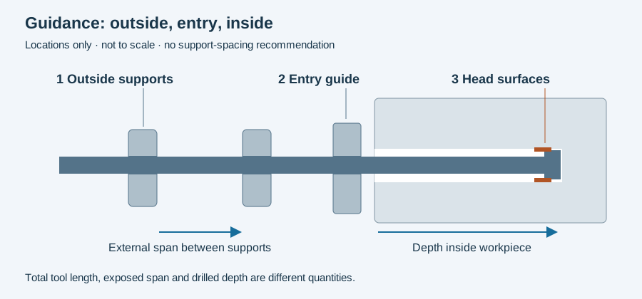
The guidance diagram below shows mounting alongside the separate external contacts. Use the RFQ worksheet to retain the assembly and requested check. Continue to bushings/workholding for entry and part support, or bore straightness for interior measurement coverage.
Revision note
October 8, 2026: revised the technical explanation and connected reading after source review. Original publication date and URL retained.