Deep hole drilling tooling includes the cutting tool and the interfaces that let it operate. A head description alone leaves out mounting, starting guidance, outside support and fluid delivery. Read the assembly as connected functions before comparing individual products.
Cutting and bore-contacting guidance
The botek single-flute catalogue distinguishes tool constructions and identifies nose grind and peripheral guide contour. These features belong to the head’s cutting and bore-contact behavior. They are different from a bushing at the workpiece entry.
The BTA catalogue separately identifies solid-drilling, counterboring and pull-boring families, with different connection and wear-component arrangements. Preserve the operation type as well as the nominal diameter when identifying the tool.
Mount and support the actual construction
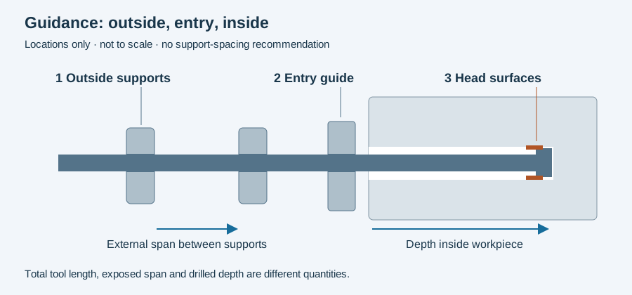
UNISIG’s machine description separates the spindle, entry bushing, chip box and outside whip guides. Its chip box maintains the bushing/spindle alignment, while the whip guides contact the long shaft outside the part. The locations explain why changing an entry guide does not replace an outside support.
At the spindle interface, identify driver or holder, any sleeve or adapter, fitted projection and fluid connection. Two tools with the same cutting diameter need not have the same mounting feature.
Trace medium all the way to return
Gun-drilling supply passes through the tool and returns with chips along the external flute. BTA uses a different supply/return architecture. Follow the selected method’s circuit before evaluating a pump, pressure head or rotating interface.
The coolant-component article maps filtration and clean supply upstream. The rotary-union article addresses a particular rotating boundary. Those functional connections help distinguish an assembly requirement from a product name in a bill of materials.
A tool change can change several interfaces
When a replacement includes a different head, driver or service state, retain that configuration with the production interval. A tool identifier should lead to what was installed, not merely to an original purchase description.
For a comparison, state which components are held constant and which change. Then preserve the inspected result of the actual bore. A successful connection or nominal product capability is one part of that evidence, not the delivered characteristic itself.
The guidance-location figure below provides a first map of those contacts. Use the RFQ worksheet to retain interfaces for a proposed assembly. Continue to holders for assembled runout and mounting, or coolant components for the full return/supply route.
Revision note
October 8, 2026: revised the technical explanation and connected reading after source review. Original publication date and URL retained.