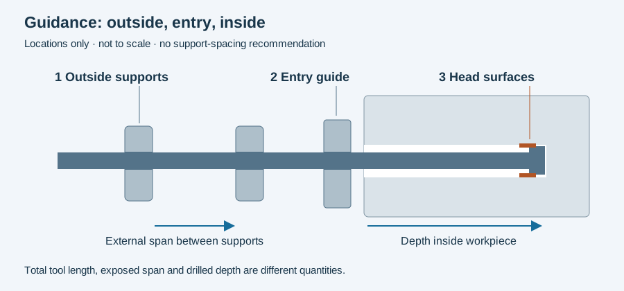
Deep hole drilling guide pads travel with the tool head inside the bore. An entry bushing and an outside shaft support act at different locations. Identifying which contact is under discussion is the first step toward interpreting a pad-selection or maintenance issue.
A contact that belongs to the cutting system
The botek single-flute catalogue describes guide pads supporting the asymmetric cutting forces against the bore wall. It identifies peripheral contour and nose grind as parts of the tool’s behavior, including surface and dimensional outcomes. A pad is consequently part of a defined head geometry rather than an interchangeable spacer.
The source describes that relationship for its tools. It does not establish one pad material, clearance or contour for every gun-drilling and BTA construction.
Construction changes the service question
The BTA catalogue distinguishes brazed and replaceable-component head constructions. Some named brazed heads are regrindable; other assemblies use separate wear components. Start with the actual type before deciding what a pad change or tool service includes.
Replacing a pad, regrinding an edge and repairing a head body are separate operations. Record which was performed and what geometry was checked afterward. Their effects should not be collapsed into a single “refurbished” tool status.
Preserve where condition was observed
When examining a tool, identify the pad, its orientation and the production interval. Keep deposits, scratches, fracture or other observed features as observations until the investigation supports a cause. Compare them with the relevant bore location and required measurement, rather than treating a photograph as a complete dimensional report.
That record is particularly useful when the cutting insert and pad are serviced at different times. Tool identity alone may remain unchanged while the contact configuration changes.
A sensor underneath a pad measures another location
The 2022 sensor-integrated gun-drill paper places temperature and acceleration sensors beneath a front pad. Its near-zone observations illustrate why contact position matters. They do not give a universal pad-temperature limit or measure the complete bore wall.
For a sensing proposal, keep the mechanical contact, sensor position and inferred quantity separate. The newer thin-film guide-pad proposal discussed in smart tooling is another design route, requiring its own validation.
The guidance-location figure below separates bore-contacting surfaces from external guides. Use the incident worksheet to retain the observed tool and affected bore. Continue to BTA remanufacturing for the returned assembly, or tool-wear investigation for the relationship between observed condition and service endpoint.
Revision note
October 8, 2026: revised the technical explanation and connected reading after source review. Original publication date and URL retained.