Set ejector drilling parameters from the selected tool
Start with the current tool supplier’s data for the material grade and condition, tool diameter and geometry, depth, machine and coolant. This page explains parameter selection and units; it does not assign one cutting-data table to every tool.
Record the inputs
| Input | Required detail |
|---|---|
| Material | Grade, heat treatment/hardness and blank condition |
| Tool | Exact head/drill family, cutting material, geometry and condition |
| Bore | Diameter, full depth, pilot, bottom and intersections |
| Equipment | Spindle, feed, support and available travel |
| Coolant | Fluid, delivered pressure/flow, filtration and temperature |
Keep speed and feed units explicit
The Sandvik Coromant metric formula sheet defines these conversions. The inputs below are assumed for illustration.
For diameter D in mm and cutting speed vc in m/min:
1Spindle speed n (rev/min) = 1000 × vc / (π × D)
2Feed speed vf (mm/min) = f (mm/rev) × n (rev/min)
For an assumed D = 10 mm, vc = 60 m/min and f = 0.02 mm/rev, n is approximately 1,910 rev/min and vf approximately 38.2 mm/min. This is a unit-conversion example, not a recommended cutting condition.
Process-specific checks
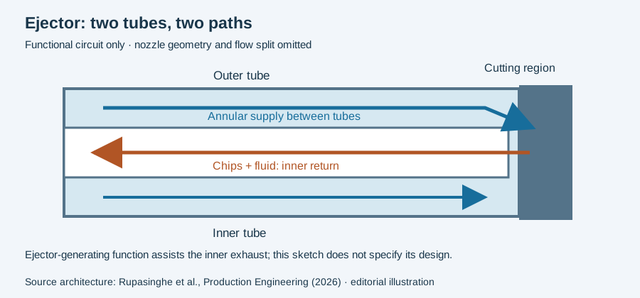
Confirm the chosen head and inner/outer tube combination, connector and coolant delivery. The required flow belongs to this system and bore, not a diameter-only universal table. Investigate blocked or unstable chip return before adjusting cutting conditions.
Establish a documented starting condition
Use the supplier’s applicable values and stated operating sequence. Verify the coolant at the actual tool condition and confirm guidance/clearance before evaluating the cut. Record chip behavior, tool wear and measured bore results; change one identifiable setting at a time within the approved application limits.
Sources and further reading
Tool/process reference. Product-specific tables and instructions take precedence over generic examples. Use the quality guide to define the result being optimized.
Separate input settings from the endpoint being tested
In a parameter record, keep cutting speed, feed convention, tool diameter and fluid condition alongside the result used to end the comparison. A stable-flow endpoint and a final bore-inspection result are separate records. The ejector study linked above investigates its defined chip-blockage criterion; that criterion is not a universal machine-stop threshold.
For a hypothetical unit check, suppose an identified tool’s approved data specify D=30 mm, vc=60 m/min and fn=0.2 mm/rev. Using the drilling conversion formulas:
1n = 1000 × 60 / (π × 30) = 636.62 rev/min
2vf = 0.2 × 636.62 = 127.32 mm/min
These are deliberately assumed conversion inputs, not this site’s recommended settings or a reproduction of a trial. Converting them correctly does not establish the appropriate fluid flow or the tool’s entry procedure.
Keep the original recommendation and its conditions with the calculation. If the proposal changes the head design, material or delivery arrangement, record that difference before transferring a setting. Read the tested-head comparison for why one research outcome cannot be turned into a family-wide recipe.
Revision note
October 8, 2026: revised the technical explanation and connected reading after source review. Original publication date and URL retained.