Review the ejector process through the actual assembly drawing, supplier instructions and measurement plan. Identify the head, tube arrangement, fluid connections and machine interface before discussing operating proposals. Keep a general process diagram separate from instructions approved for the selected system. Assess completion through the specified inspection stage rather than assuming a drilled hole is an accepted part.
Follow the two tubes through the fluid circuit
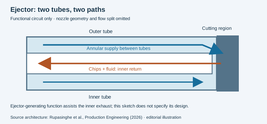
UNISIG identifies supply between the inner and outer tubes and return through an adapter ahead of the spindle. TU Dortmund’s ISF describes nozzle diversion as the mechanism producing lower pressure in the inner tube. These accounts explain the process arrangement without establishing the reader’s operating window. UNISIG ejector overview, TU Dortmund ISF ejector project.
Keep the head, tubes and adapter identified on a route schematic. That schematic helps relate the supply and chip-return observations to their actual places in the assembly.
A process explanation is not a commissioned installation
Describe the entry, cutting and exit stages against the applicable machine and tooling instructions. Record the configured system before any application trial. The cited research project discusses investigation and modeling; its objectives are not a completed production acceptance. This page introduces the process, while the tooling and troubleshooting pages handle component fit and incident evidence separately.
Trace the return from the cutting zone
Follow the annular supply to the head, then the chip mouths into the inner return tube. The 2026 journal paper describes this architecture. The drawing below is a functional sketch, not a nozzle or tube-sizing instruction.
An observation at the discharge occurs after the mixture has passed through several interfaces. If returning chips change, identify the observed point and corresponding operating interval before locating a cause. A recovered return after multiple setup changes establishes a combined recovery, not which single interface was responsible.
The machine record should preserve the installed head, inner and outer tubes, connection and supply arrangement together. Comparing a head in isolation leaves the rest of the exhaust system undefined. Where a circuit reading is used, preserve the point, units and operating state rather than comparing it with a number taken elsewhere during idle circulation.
The next question determines the next page: use coolant investigation for delivery evidence, or particle simulation to understand a published model’s treatment of the head region. Neither supplies a substitute for the installed machine’s procedure.
Revision note
October 8, 2026: revised the technical explanation and connected reading after source review. Original publication date and URL retained.