Distinguish a qualitative Venturi discussion from the design of a specific ejector tooling assembly. Ask the supplier to document the geometry, interfaces and operating basis used for its system. Compare measured behavior with that basis and keep the observation locations explicit. This article supplies review questions rather than fabrication dimensions or a universal performance calculation.
Use the source’s actual ejector mechanism
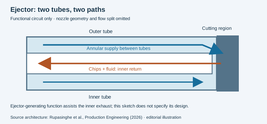
TU Dortmund’s ISF describes part of the fluid flow being diverted through ejector nozzles into the inner tube, reducing its pressure and assisting return. The original account provides a more specific mechanism than simply labeling the system Venturi. It does not establish that all assemblies use one textbook throat geometry. TU Dortmund ISF ejector project.
For a tooling proposal, ask which components create the described effect and how the configured system will be verified.
Simulation objectives are separate from validated results
The project account describes a test rig and SPH modeling work to investigate the effect. Keep these research objectives distinct from a completed validation report. A later simulation claim should identify geometry, conditions, validation measurements and the result being compared. No nozzle dimensions, universal suction level or flow-saving percentage is adopted here from the project announcement.
The principle does not determine one nozzle geometry
The journal explanation associates internal chip exhaust with the ejector effect. That process description identifies a function; it does not supply one pressure ratio, clearance or nozzle dimension suitable for all tube assemblies.
When reading a proposed design, distinguish the ejector-generating arrangement from the fluid passages near the cutting zone. A change to one region should remain visible instead of being summarized as a universally better ejector. The actual comparison needs its inlet conditions, passage geometry and reported output together.
An illustrative review question is whether a proposed head change was examined with the same tube and supply conditions as its reference. If those conditions changed as well, the outcome belongs to the complete tested combination. This matters even when both drawings are described using the same physical principle.
Use the process-path explanation to locate the function and the model interpretation to read a design study’s assumptions. Dimensioning and operating instructions require the actual system’s documentation.
Revision note
October 8, 2026: revised the technical explanation and connected reading after source review. Original publication date and URL retained.