Gun Drilling, BTA and Ejector: Compare the Fluid and Chip Routes
Compare conventional gun drilling, BTA and ejector by their supply, return and machine-interface architecture before considering a change of process.
Understand gun drilling coolant and chip paths, then choose the relevant tooling, setup and bore-quality reading.
Gun drilling sends cutting fluid through passages inside the tool. The return stream carries chips along the outside groove. UNISIG describes this arrangement in its English process explanation and German Einlippenbohren overview. That distinction separates gun drilling from the internal chip return used in BTA drilling.
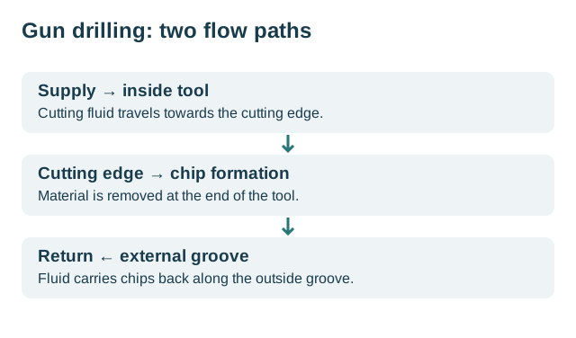
Editorial mechanism sketch, not a tool drawing or a coolant specification. Based on the two process descriptions above.
The sketch explains a route, not a pressure setting. A pressure reading without its measurement location, fluid condition and selected tool leaves the actual supply at the edge unresolved. Begin with the tool maker’s application documentation before choosing a trial setting.
Two catalogue entries can share the name “gun drill” while differing in cutting-section construction and service requirements. Read gun drill geometry and types alongside the manufacturing-process explanation. Identify the exact assembly under discussion; a service procedure for one construction is not a procedure for every gun drill.
| Question at this stage | Reading route | Record for your job |
|---|---|---|
| What carries the fluid and returns the chips? | Coolant systems | Tool passages, supply measurement and return route |
| How is the selected assembly guided? | Setup and alignment | Entry guidance, support arrangement and drawing reference |
| Which setting is actually documented? | Speeds and feeds | Material condition, tool identity and approved trial scope |
A completed drilling cycle and an accepted bore answer different questions. Before a trial, connect the drawing to an inspection plan: which characteristic, at which location, using which method? Keep the resulting report with the setup record. This is our editorial route through the topic; it does not supply a universal machining recipe.
If the immediate problem is a changing chip stream or a damaged tool, move to the incident record and document what changed before selecting a cause. The articles below cover the individual parts of that investigation.
Choose your next step
Choose the question you are working on. These links organize the library; they are not machine operating instructions.
Start with the process
What Is Gun Drilling? Internal Supply and External Chip Return →Prepare tools and setup
Gun Drilling Alignment: Location, Direction and Repeatable Offset →Review parameters
Gun Drilling Speeds and Feeds: Units and a Catalogue Example →Investigate problems
Gun Drilling Troubleshooting: Choose the Evidence Path →Compare conventional gun drilling, BTA and ejector by their supply, return and machine-interface architecture before considering a change of process.
Follow the gun-drilling mechanism from entry guidance to in-bore cutting and external chip return, with operating-sequence limits kept separate.
Identify the gun drill’s cutting head, chip flute, internal fluid passage and driver, including the difference between brazed and solid-carbide …
Understand gun drilling through its fluid circuit, single-lip cutting tool and guidance, then distinguish the process from its achieved bore quality.
Read coating names as supplied service options, then compare identified tool states and accepted output without assuming a universal coating winner.
Separate gun-drill construction from nose-grind geometry, peripheral guide contour and fluid passages when identifying or comparing actual tools.
Explain guide-pad and ground-land contact, distinguish it from entry and outside supports, and preserve the actual peripheral geometry during service.
Define the actual gun-drill geometry, service scope and returned inspection before connecting a regrind to the next machining interval.
Understand how the spindle, entry guidance, whip supports, chipbox and fluid system work together when assessing a gun-drilling machine.
Compare a gun drilling pilot hole with an external guide bushing; identify entry references, tool guidance and the dimensions requiring tool-specific …
Distinguish external whip-guide support from entry and in-bore guidance, and follow the supported tool spans as drilling advances.
Interpret the IFW/ISF dynoSpan CFRP-shaft concept, its proposed interfaces and fluid circuit, and the evidence needed before application claims.
Evaluate a gun-drilling precision claim by its specified characteristic, inspected locations, reference system and measurement evidence.
Start gun drilling troubleshooting from the observed defect, separate competing explanations and use a controlled comparison with an inspected outcome.
Connect each required bore feature to its measurement programme, evaluated coverage and identifiable inspection result.
Investigate vibration by matching the observed signal, resulting bore surface and guidance configuration to the same drilling event.
Investigate a broken gun drill by separating when damage was observed, possible contributors and the evidence from a subsequent controlled comparison.
Interpret a surgical-instrument gun-drilling application through the blank, bore sequence, clamping, transfer and inspection rather than the industry name.
Compare gun drilling materials using grade, supplied condition and tool-specific catalogue classifications; separate listed guide values from measured …
Build comparable gun-drilling quotations from supplied material, setup, tool service, inspection and delivery, with a stated accepted-output boundary.
Calculate cost per accepted hole and derive when additional rework raises or lowers that average, using explicitly assumed costs and output.
Compare service proposals by their machining scope, identifiable bore requirements and inspection deliverables rather than a generic precision claim.
Compare carbide-head and solid-carbide gun drills using documented construction, working geometry and interfaces rather than the material label alone.
Calculate relative rotation for a counter-rotating tool and workpiece, then distinguish speed arithmetic from evidence of improved bore geometry.
Track a physical gun drill across production, regrinding and recoating, retaining each returned configuration and its accepted output.
Compare documented gun-drill materials and joints, and separate those construction facts from an unverified factory production recipe.
Trace gun-drilling fluid supply and return, distinguish pressure from flow and retain the actual measurement point and tool configuration.
Distinguish lower-pressure liquid supply from a documented compressed-air/oil spray-mist system, and assess the named tool and application scope.
Investigate gun drilling alignment with fixed coordinates, entry-location and direction examples, then compare documented setup changes with bore results.
Convert gun drilling cutting speed to rpm and feed per revolution to feed speed; read a tool-specific catalogue example without treating it as a universal …
Identify VDI gun-drilling and related process references, distinguish linear-size specifications, and retain the edition and required acceptance evidence.
Distinguish listed small-diameter gun drills from a specified machine application, and connect geometry, guidance, fluid delivery and bore inspection.