Counter-rotation turns the tool and workpiece in opposite directions. Its relative rotation is different from the rpm displayed for either spindle, so a cutting-speed calculation needs both motions and their direction convention.
One cutting relationship, two spindle readings
For coaxial rotations, assign a signed angular speed to each spindle. The relative speed is the magnitude of their difference. With opposite directions, the magnitudes add.
In an assumed arithmetic example, a tool runs at +4,000 rpm and a workpiece at −1,000 rpm. Their relative rotation is 5,000 rpm. For an assumed 4 mm cutting diameter, the circumference calculation gives:
1Relative rpm = |4,000 − (−1,000)| = 5,000 rpm
2Cutting speed = π × 4 × 5,000 / 1,000 = 62.83 m/min
These are invented inputs illustrating the motion calculation. They are not recommended settings or a claim that a particular machine permits them. If both spindles instead rotated in the same direction at those magnitudes, the relative speed would be 3,000 rpm. Direction therefore belongs beside each recorded speed.
The conversion tool below converts a specified cutting speed and diameter back to rpm. Entering the example’s 62.83 m/min and 4 mm returns approximately 5,000 rpm, with rounding. That result is the relative rotation for this example; it does not assign the speeds of the two spindles. The tool does not calculate the counter-rotation split.
What a supplied machine example establishes
UNISIG’s 2024 UNI20-4-750-CR announcement describes a four-spindle machine with workpiece counter-rotation. Its German publication also presents improved bore accuracy and straightness as a manufacturer claim.
The announcement does not provide matched bore profiles, an effect size or an inspection uncertainty for comparing two motion arrangements. It establishes an offered configuration and the supplier’s stated rationale, rather than a guaranteed improvement for every workpiece.
Keep motion and inspection in the same comparison
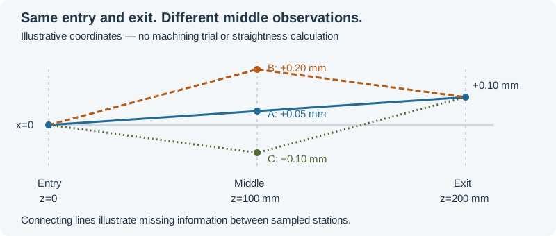
A meaningful application comparison identifies the tool and material, both spindle motions, the feed convention, entry guidance, clamping and measured characteristics. An entry/exit comparison alone may miss differences inside the bore; the schematic below illustrates that measurement-coverage problem using assumed paths.
Changing workpiece rotation also changes the configuration being assessed. Preserve the inspected component’s relation to its external datums instead of describing all geometric outcomes simply as “accuracy.” Continue to setup alignment for those relationships and quality control for the delivered evidence.
Revision note
October 8, 2026: revised the technical explanation and connected reading after source review. Original publication date and URL retained.