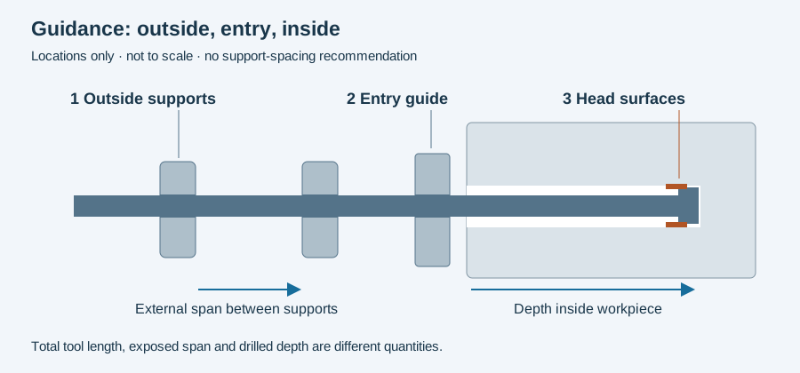
Gun drill guide pads or lands travel with the cutting head and contact the bore wall. An entry bushing and an external whip guide remain separate machine-side arrangements. All three provide guidance or support, but at different locations.
A ground land need not be a replaceable pad
Gühring’s EB80 explanation describes guide lands ground into the carbide head’s circumference. That construction differs from a head carrying replaceable guide elements. The phrase “replace the pads” is consequently incomplete until the actual tool design is identified.
The location diagram below places the head surfaces inside the workpiece, the bushing at entry and the shaft supports outside. A report that says “guidance renewed” should identify which of those components was serviced. Their effects cannot be separated later if the record combines them into one unnamed intervention.
Cutting and guiding contact belong to the same head
Page 15 of the botek catalogue describes cutting forces pressing head guide surfaces against the bore wall and a resulting smoothing effect. It discusses peripheral contour separately from nose-grind geometry. This explains why the head should not be understood as a cutting edge followed by an unrelated support accessory.
The description is a manufacturer’s mechanism explanation; it does not establish a surface-texture value for every material and setup. The bore’s inspected texture and geometry still need their own measurement conditions and locations.
Preserve the circumferential form
Two heads with the same nominal cutting diameter can have different guide arrangements. Keep the supplied peripheral-form designation or drawing with the tool identity. An orientation-marked head image can help locate an observed condition, but it is not a substitute for the required geometric measurement.
The botek contour table on page 16 also cautions that certain forms are not directly measurable in the usual diameter sense. A diameter result needs the intended geometry and method; forcing every asymmetric head into one two-point measurement can create a misleading comparison. This article does not assign a general wear limit or approve reshaping the guide surfaces.
Relate service to the next bore interval
Retain the tool’s delivered state and the work performed before comparing subsequent bore observations. If an entry bushing, fluid condition or tool grind also changed, preserve those changes with the interval. Otherwise a changed bore result cannot be attributed to the guide surfaces alone.
Use the quality worksheet to define which bore characteristics and depth locations will be inspected. Continue to geometry types for the independent specification fields or regrinding for the service boundary.
Revision note
October 8, 2026: revised the technical explanation and connected reading after source review. Original publication date and URL retained.