Gun drilling speeds and feeds start with the selected drill’s cutting data. A conversion can check the arithmetic; it cannot choose a suitable cutting speed or feed for an undocumented tool and material combination.
Convert cutting speed and feed with explicit units
The Sandvik Coromant metric drilling formula sheet defines:
1n (rev/min) = 1000 × vc (m/min) / [π × D (mm)]
2vf (mm/min) = fn (mm/rev) × n (rev/min)
Here D is the cutting diameter, vc is cutting speed, fn is feed per revolution and vf is linear feed speed. A value entered as mm/min is not interchangeable with mm/rev. The speed and feed calculator performs these conversions and shows the units alongside the result.
A worked example from one catalogue row
The botek single-lip and two-lip drill catalogue, printed page 10, gives cutting data for Type 113 solid-carbide drills. Its austenitic stainless-steel class, labelled Ni > 8% and Cr 18–25%, lists vc = 30–40 m/min. The 2.0–2.49 mm diameter row lists fn = 0.0050–0.0070 mm/rev.
Take D = 2.00 mm, vc = 30 m/min and fn = 0.0050 mm/rev, using the lower ends of those listed ranges:
1n = 1000 × 30 / (π × 2.00) = 4,774.65 rev/min
2vf = 0.0050 × 4,774.65 = 23.87 mm/min
This is a catalogue-reading example, not a demonstrated production trial. The catalogue class alone does not identify a particular stainless grade, heat treatment, bore depth or machine. Do not transfer the row to another drill construction: the same catalogue separates Type 113, Type 113 HP and brazed Type 110 data.
Read the whole cutting-data entry
Before converting a value, keep its tool family, diameter band, material classification and notes together. Ask the supplier to resolve a missing grade or operating condition rather than selecting the nearest-looking number. Document the actual drill designation and catalogue revision with the setup record.
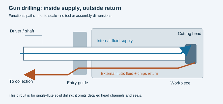
Coolant delivery, entry guidance and tool condition are separate inputs. A correct rpm calculation does not establish that the machine can deliver the required coolant flow or that the pilot and guide arrangement matches the tool.
Validate a change against recorded results
Keep the original and revised settings, chip observations, depth at which a symptom appears, and inspection results together. Change an approved variable deliberately so the comparison remains interpretable. Use the incident worksheet when a parameter change is part of a fault investigation.
The arithmetic above uses a general drilling conversion. Tool-specific starting data and actual bore results remain the basis for evaluating the process.
Correction
October 8, 2026: corrected the Type 113 austenitic feed range for the 2.0–2.49 mm diameter band to 0.0050–0.0070 mm/rev. The earlier example incorrectly copied the adjacent 1.8–1.99 mm row. The lower-end linear feed example is 23.87 mm/min.
A correct conversion can exceed the machine configuration
Consider a separate, explicitly assumed example: D = 2 mm, vc = 40 m/min and a spindle ceiling of 6,000 rpm. The formula gives approximately 6,366 rpm, above that assumed limit. At 6,000 rpm the corresponding peripheral speed is approximately 37.70 m/min.
This arithmetic identifies a constraint; it does not select a validated cutting setting. Changing rpm also changes feed in mm/min when feed per revolution is held constant. The applicable tool instructions, workpiece condition and machine/fluid configuration still have to support the selected operating point.
Keep the published range, the chosen trial input, the converted command and the observed result separate. The calculator performs the conversion. The RFQ or trial record supplies the context it cannot infer. Continue to material interpretation for source selection and quality control for the endpoint against which a trial is assessed.
Revision note
October 8, 2026: revised the technical explanation and connected reading after source review. Original publication date and URL retained.