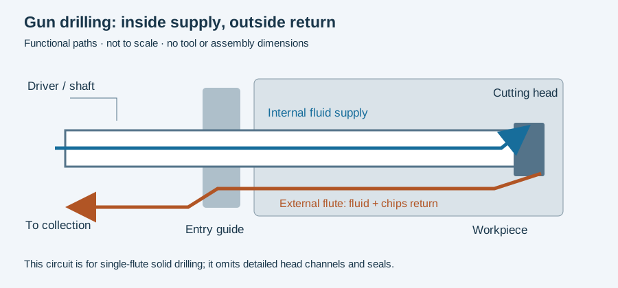
Gun drilling connects three mechanisms: guidance establishes where the tool enters, relative rotation and feed create the cut, and fluid transports the resulting chips out of the bore. A useful explanation follows all three rather than treating the drill as an unusually long twist drill.
Before a bore can guide the head
Page 5 of the botek catalogue identifies the gun drill as a single-edged tool requiring a bushing or pilot hole at entry. Before the cutting head has an established bore around it, that external arrangement supplies the guidance.
Once the head advances, its guide surfaces contact the bore wall. The tool length remaining outside the part still needs its own support. The second diagram in whip-guide support shows why increasing drilled depth and decreasing external unsupported length are different quantities.
Relative motion produces the cut
UNISIG’s machine overview describes tool rotation, workpiece rotation or both. Feed advances the tool relative to the component. A spindle-speed number must therefore be read alongside the motion arrangement; tool rpm alone is not necessarily the relative cutting speed when the workpiece also rotates.
For a speed/feed calculation, the conversion worksheet below converts specified cutting speed and diameter into rpm, then specified feed per revolution into linear feed. It does not choose those inputs or establish that a machine supports the resulting motion.
Chips have a continuous return route
The botek description routes fluid internally to the working end, then fluid and chips back along the external V-groove. Follow that return to collection as well as the supply to the head. The cutting zone is where the two routes meet; an obstruction or an altered tool passage cannot be understood solely from a pump’s displayed setting.
A chip collected after an interruption belongs with its machining interval. If material, grind or cutting inputs changed, preserve that context before comparing it with an earlier sample. Chip appearance alone does not establish the cause of a bore defect.
Mechanism is not a universal operating cycle
The English and German botek catalogues give different wording on page 34 about switching off coolant during withdrawal. The English version places shutoff before retraction; the German version places it after retraction. This discrepancy prevents using those publications as one general cycle instruction.
Actual entry, rotation, fluid and withdrawal commands need the applicable tool and machine documentation for the specified setup. Read pilot holes and bushings for entry requirements and counter-rotation for interpreting simultaneous spindle motions.
Revision note
October 8, 2026: revised the technical explanation and connected reading after source review. Original publication date and URL retained.