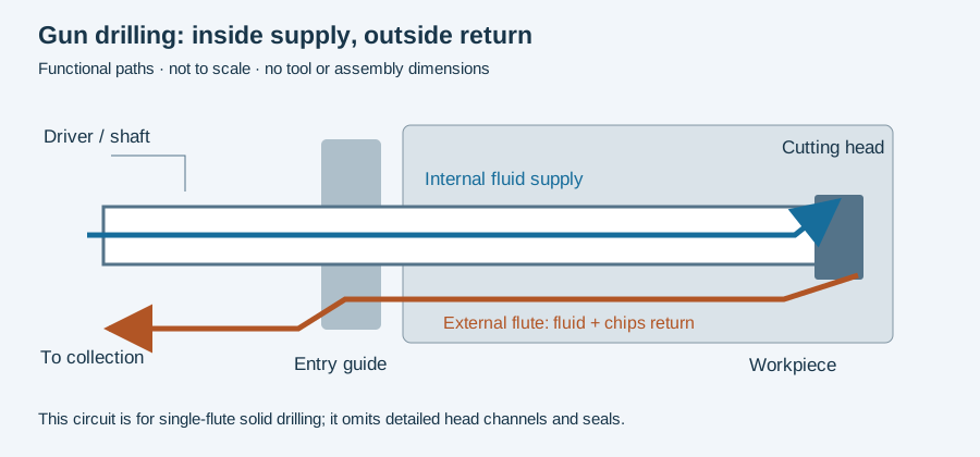
A gun drill is the cutting tool; the pump, entry bushing and external support carriages belong to its machine setup. Understanding what is physically part of the tool makes construction and service descriptions much less ambiguous.
Read the tool from front to back
TBT’s construction description identifies a cutting head, shaft and clamping sleeve. In its brazed-head arrangement, the head may be solid carbide or a steel body carrying carbide elements; the shaft and sleeve are steel, joined to the head by brazed connections.
At the working end, the cutting geometry forms the chip. The head also carries surfaces that guide against the bore wall. Behind it, the shaft provides both an internal fluid route and an external chip-return flute. The driver or sleeve connects the tool to the machine. These locations are shown in the circuit sketch below; the sketch is not a section drawing for manufacturing a tool.
“Solid carbide” needs a construction boundary
TBT describes its solid-carbide variant as a head and shaft made from one carbide blank, connected to a steel clamping element. Page 6 of the botek catalogue describes a corresponding Type 113 construction: a carbide cutting portion and shaft joined to a steel driver.
Thus a carbide head on a steel shaft and a carbide head-and-shaft body are distinct tools. Both can contain a brazed connection. Counting joints or reading “carbide” in a quotation is insufficient to identify the construction.
This distinction matters when a damaged area is described. A worn cutting end, a damaged shaft and a defective driver connection are different service questions. Keep the tool identity and the location of the condition together, rather than recording only “gun drill worn.”
The shape at entry is not the entire setup
Gühring’s EB80 explanation describes guide lands ground on the head’s circumference and a separate pilot-hole or bushing requirement at entry. A guide land travels with the cutting tool. A bushing remains part of the external setup. Replacing one does not renew the other.
For identification, retain the head construction, nose-grind designation, peripheral form, working length and driver interface. Those describe different features; an outside diameter alone cannot define them all.
Continue to construction and geometry types when comparing tool descriptions, or guide surfaces when interpreting the head. The RFQ worksheet provides a place to retain the complete identity before an application or service enquiry.
Revision note
October 8, 2026: revised the technical explanation and connected reading after source review. Original publication date and URL retained.