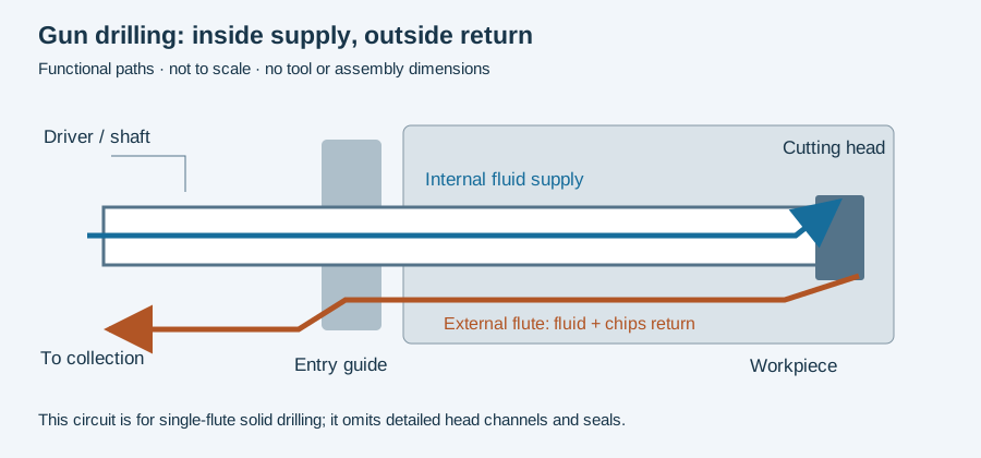
Gun drilling is a deep-hole cutting process in which fluid reaches the cutting zone through the tool and carries chips back along an external flute. The route of those chips, rather than a particular depth-to-diameter number, identifies the arrangement discussed here.
Trace the circuit from the cutting end
Page 5 of the botek single-flute catalogue describes internal fluid supply and return through the V-shaped groove. Fluid supplies the cutting zone and lubricates the tool periphery. The groove provides a return passage between the tool and the bore; it is not a second internal tube.
The diagram below separates the blue supply route from the orange return. A head photograph may show a coolant opening but cannot describe the collection, filtering and supply equipment connected to it. That equipment belongs in the process explanation because returned fluid must reach the machine’s collection system before reuse.
Compare this with BTA drilling, where the supply is outside the tube and return inside it, and ejector drilling, which uses a double-tube arrangement. These are circuit distinctions. They do not establish a universal diameter at which a different process becomes more economical.
The cutting head and the entrance need different guidance
The same catalogue describes a single-edged tool that requires a guide bushing or pilot hole at entry. Once cutting takes place inside the bore, guide surfaces on the head contact the bore wall. External supports address the tool length still outside the workpiece.
This explains an apparent contradiction in brief descriptions: an in-bore self-guiding tool can still need entry guidance. The two statements refer to different locations and stages. A finished bore also depends on the relationship between that guidance, workholding, tool and machine.
What the process name establishes
“Gun drilled” describes the manufacturing route. It does not specify a diameter tolerance, a datum-related axis, a surface-texture limit or inspection coverage. Those requirements must accompany the feature on the component drawing.
For example, an assumed drawing may require a bore to remain aligned with an external cylindrical datum. Measuring only the entry diameter cannot answer that requirement. The process introduction therefore leads to both tool anatomy and how the mechanism works, followed by a separate quality review when a real part is specified.
Use the RFQ worksheet to assemble that part’s feature, supplied material and delivered measurement requirements. It is a way to describe a job, not a source of cutting parameters.
Revision note
October 8, 2026: revised the technical explanation and connected reading after source review. Original publication date and URL retained.