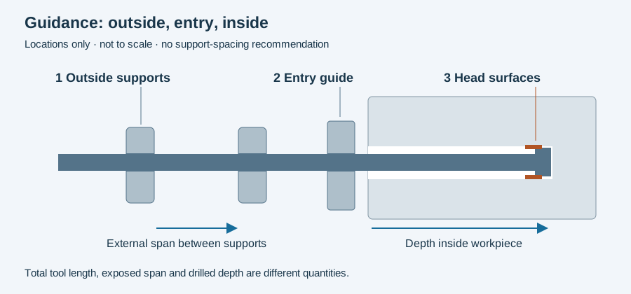
A whip guide supports the gun drill outside the workpiece. It does not replace the entry bushing or the guide surfaces on the cutting head. That location is the first detail to establish when a report says that “tool guidance” was checked.
The supported span changes during travel
UNISIG’s machine overview describes bearing-and-insert supports around the tool shaft. Some machines use traveling carriages that collapse together as the tool advances; shorter arrangements may use a stationary support.
The diagram below separates outside support, entry guidance and head contact inside the bore. As the cutting head advances, the exposed tool spans can change. Total tool length, drilled depth and distance between supports are therefore three different dimensions. Recording one does not establish the others.
Page 34 of the botek catalogue defines unsupported length using the spans between supports or a guide arrangement. Its guidance is specific to named constructions and diameters. A total hole-depth ratio should not be substituted for the support-length variable in that source.
Match the support to the shaft that passes through it
The catalogue’s shaft discussion on page 17 describes fluted shafts and special arrangements with round portions in the support region. This is a construction detail, not permission to use any insert with any shaft. Retain the actual tool section, support insert and carriage configuration together.
A drawing that shows the support at the initial position alone may also omit what happens near the end of travel. During a setup review, identify the relevant positions and the spans present at each. Any allowed spacing or operating limit should come from the applicable tool/machine documentation, not a universal “supports every N diameters” rule.
Interpreting a vibration report
Keep the observed event tied to spindle motion, feed position and the tool’s exposed arrangement. If a symptom occurs only in part of the travel, that location is useful evidence; it does not prove that the support caused it.
An illustrative incident record might distinguish a symptom before entry, during established cutting and near a support-carriage transition. Those are observations to compare with the actual setup. Changing a support and a cutting input simultaneously would make their individual contributions harder to assess.
The incident worksheet below retains the event and setup context. Read pilot holes and guide bushings for the entrance, and guide pads for the surfaces traveling inside the bore. Together these pages describe the three guidance locations without collapsing them into one adjustment.
Revision note
October 8, 2026: revised the technical explanation and connected reading after source review. Original publication date and URL retained.