The part drove the machine arrangement
UNISIG’s Alta Precision report describes a Montreal landing-gear strut application using a B700 drop-bed BTA machine. It reports a 9-inch [230 mm] bore more than 7 feet [2.1 m] deep and a 54-inch [1,370 mm] swing for the asymmetric workpiece. The bracketed metric figures are the source’s rounded values.
The account describes counterrotation and internal-profile work involving BTA drilling, counterboring and forming. Its page displays March 4, 2017 and January 20, 2025 dates. We treat it as historical coverage, not a new 2026 installation. These details are the manufacturer’s account, not measurements independently witnessed by this site.
What the envelope adds to the comparison
Our reading of the case is that bore diameter and depth do not describe the whole proposed job. The surrounding part, its rotation envelope and the included internal operations belong in the same equipment enquiry. A nominal capacity comparison that omits those items leaves the actual configuration unresolved.
Use the BTA topic guide to identify the flow and entry interfaces. Then put the part drawing, rotation arrangement and included operations into the RFQ worksheet. Request a configuration drawing against that enquiry rather than matching only two headline dimensions.
What the report does not establish
The published account does not provide numerical conformity results, a complete cycle-time comparison, accepted-output counts or an independently inspected baseline. It therefore cannot establish a tolerance, yield or total-cost advantage for a different landing-gear part.
For a purchasing comparison, add the proposed inspection method and the actual workpiece requirements. Keep any subsequent trial results with their configuration and report references. The case is useful evidence of an attributed application arrangement; those additional records are needed to evaluate your own job.
Read the two capacities separately
The case describes a profiled opening approximately 9 inches in diameter. It also gives the standard B700’s solid-drilling rating as 8 inches and counterboring rating as 12 inches. These are different operations. Turning the 9-inch finished feature into a claim of 9-inch solid-drilling capacity would erase the distinction the source makes.
The same account names counterboring and forming alongside BTA drilling. A comparison should identify the intermediate opening and the completed profile, then attach inspection to the delivered geometry. This interpretation follows the operations described in the original case; it supplies no reconstruction of the proprietary machining sequence.
The external feature changes the installation
The asymmetrical strut requires clearance and introduces off-center weight during workpiece rotation. UNISIG describes a drop bed and spindle orientation for handling this envelope. That makes the forging outline relevant even though the principal bore is internal.
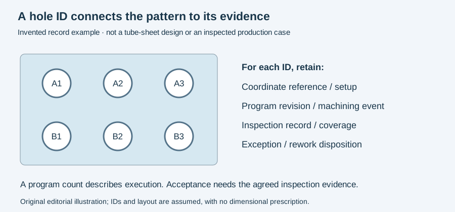
For a comparable enquiry, the RFQ should show the incoming blank, locating features, rotation envelope and required internal profile. The bore-evidence diagram below then connects inspection to part identity. The two next readings explain the wider aerospace application and the distinction between a drilled opening and later internal operations.
Revision note
October 8, 2026: revised the technical explanation and connected reading after source review. Original publication date and URL retained.