Copper-alloy deep hole drilling tables can refer to quite different tools. A twist-drill table for brass and a single-lip experiment in oxygen-free copper do not supply interchangeable settings. Two original sources make that distinction useful rather than merely cautionary.
Read the German guide’s boundary
The German Copper Institute guide, pages 62–63, describes different drilling geometries for copper materials with different chip characteristics. It explicitly sets single-lip deep drilling apart from the general recommendations. For that process, it emphasizes geometry and feed that produce an evacuable chip form.
This is a practical reason to retain the column headings when extracting a recommendation. “Copper,” a cutting speed and a feed are insufficient if the original table describes another tool. A note about tool construction can change the meaning of the entire row.
A TU1 experiment makes chip behavior measurable
Han and colleagues’ 2025 original paper uses a 10 mm botek Type 113 tool in 500 mm-long TU1 oxygen-free copper specimens. The response-surface design examines feed per revolution, cutting speed and cutting-fluid pressure. Its responses are a chip-volume ratio and a chip deformation coefficient.
Those response definitions matter: a chip photograph and a scalar chip coefficient are related evidence, but they are not the same observation. Preserve the definition alongside the picture so the reader knows what the optimization actually minimizes.
The paper distinguishes fitted-model predictions from a physical confirmation using rounded operating inputs. The confirmed responses differ from the predictions. That separation is more informative than presenting the model’s chosen combination as a universal copper recipe.
Chip success and bore acceptance occupy different rows
Our application interpretation starts with the published question: how can the selected process improve chip responses? A shop may additionally need diameter, straightness, wall texture and cycle cost. A better chip-response value does not provide a measurement of those other requirements.
For an application comparison, attach each chip collection to a bore ID and record where the corresponding wall was inspected. If an adjustment changes chip shape but wall measurements remain unchanged, that is still an informative result. If inspection fails, the chip improvement remains a process observation rather than accepted output.
Keep the exact copper grade in that comparison. Moving from TU1 to another copper alloy changes the specimen under discussion; the original experiment has not tested the replacement simply because both names include copper.
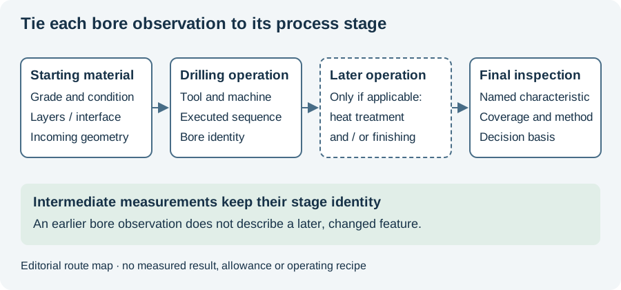
Use the bore-quality worksheet to define the missing acceptance responses. The diagram joins the material and drilling stages to inspection. Continue to the response-surface article for the experimental design, or chip evacuation for the physical return path.
Revision note
October 8, 2026: revised the technical explanation and connected reading after source review. Original publication date and URL retained.