Deep hole drilling of superalloys becomes a more useful topic when the cooling architecture and measured response are named. A complete Inconel 718 study provides an implemented experiment to read alongside research-project descriptions.
The 2026 experiment is specific
Sicking, Breer and Biermann’s open chapter uses a 2 mm TiAlN-coated twist drill with a depth ratio of 15 on a modified machine. Liquid CO2 carries cooling and an added lubricant, delivered through a separate metering arrangement.
The experiment varies CO2 pressure and compares lubricant formulations. Its tool-life criterion is a stated wear width or tool failure. Increasing pressure also changes CO2 delivery, so pressure and material flow are not independent effects in that arrangement.
The results do not establish a general rule that higher pressure gives longer tool life. The formulation and experimental variability belong in the interpretation.
Project goals and measured results have different dates
The German institute project description explains planned investigations of chip formation, microstructure and wear with cryogenic minimum quantity lubrication. It is useful context for the research question. The later chapter supplies its own executed methods and results.
Read the two together chronologically. A project intention should not be treated as a completed result, and a particular later experiment should not be expanded into every benefit envisaged by the project.
Where does the result transfer?
Our application comparison retains the actual Inconel 718 specimen and the twist-drill architecture. Hastelloy, Waspaloy and another nickel-alloy supplied state need their own comparison. A larger BTA head also changes the tool and fluid geometry; matching a lubricant name does not reproduce the experiment.
An application trial should preserve the wear endpoint used to stop the test and the bore acceptance criteria. A longer drilling path can be informative even if a required surface characteristic fails earlier. Conversely, a conservative tool-change interval can produce accepted bores without proving that maximum tool life has been measured.
Record delivery where it was measured
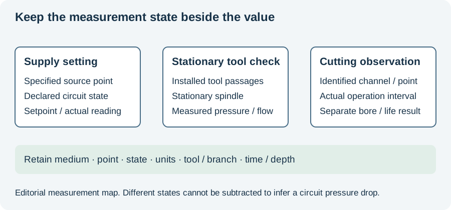
The pressure/flow-state figure separates the configured system, measurement location and operating phase. That distinction is particularly useful when comparing pump settings with conditions at a rotating interface or the tool. Keep the medium and mixture architecture visible alongside the number.
Use the incident worksheet for a delivery interruption or unexpected wear progression. Continue to cryogenic drilling parameters for the experiment’s pressure/flow interpretation, or the nickel-superalloy BTA tool page for why a boring-tool publication describes a different operation.
Revision note
October 8, 2026: revised the technical explanation and connected reading after source review. Original publication date and URL retained.