Ultrasonic deep hole drilling of titanium can refer to a combined tool, motion and programming study. The complete 2025 CSME paper by Liao and colleagues contains two comparisons that answer different questions: drilling responses and programming effort.
What was physically tested?
The original paper and downloadable full text use a 2 mm, two-flute carbide twist drill, Ti-6Al-4V round stock, cutting oil and a 20 kHz ultrasonic holder. The L9 design has four factors with three levels: rotational speed, linear feed, peck depth and ultrasonic current. Each design row was drilled twice.
Its combined response gives equal weight to thrust and roughness. The confirmation compares a selected combination with the best observed design row. Every current level in that design is nonzero; it is not an ultrasound-on versus ultrasound-off experiment.
What does the comparison actually establish?
The design explores which combination performs better within the tested architecture and factor ranges. It does not isolate the benefit of adding ultrasound to a conventional process. These are separate experimental questions.
This distinction is useful when a presentation attributes every observed improvement to its most visible technology. Changing speed, feed, peck depth and current together describes a combined process adjustment. To quantify ultrasound’s contribution separately would require a suitable baseline with that contribution distinguished.
The two responses also remain separate engineering quantities even though the analysis combines them into one grade. A new component may weight surface texture differently or require additional geometric and subsurface measurements. A preferred grade in the paper cannot substitute for those drawing requirements.
Programming time is another comparison
The authors separately compare custom macros with Mastercam 2018. Their account distinguishes initial preparation from reuse for another part. The reported reuse advantage is a programming result; it is not a measured reduction in cutting time caused by ultrasound.
The program divides entry, normal travel and exit into distinct zones. That is a useful reading clue for the executed sequence. It does not mean the printed program can be loaded into another control or that every CAM cycle has the same limitations as the tested implementation.
Keep the application route visible
For a proposed adoption, identify the ultrasonic holder, drill, control, cooling and actual part geometry. Then establish which responses will be measured and which comparison would isolate the change of interest. Preserve setup and programming effort separately from the time spent producing accepted bores.
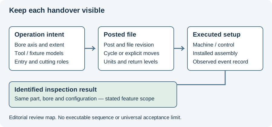
The program-handover figure below links a design and postprocessed file to the sequence actually executed. Use the conversion tool for the study’s linear-feed quantities. Continue to the titanium material overview for tool-family differences, or CNC cycle programming for control-specific behavior.
Revision note
October 8, 2026: revised the technical explanation and connected reading after source review. Original publication date and URL retained.