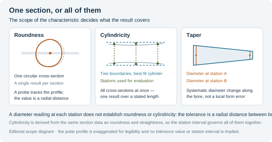
A bore can sit inside its diameter tolerance at every station an inspector visits and still fail the drawing, because diameter is not a form characteristic. Roundness, cylindricity and taper each describe something a diameter measurement cannot see, and in a deep bore the depth over which they are evaluated is itself a decision that has to be recorded.
Three characteristics, three different scopes
The distinction is easiest to hold onto if the scope of each is stated first.
Roundness applies to an individual circular cross-section. eFunda’s reference on cylindrical specifications puts it that way: roundness applies to individual circular cross sections of a surface of revolution. One section, one result.
Cylindricity applies to all cross-sections of a cylindrical surface simultaneously — the surface must lie between two cylindrical boundaries determined by a best-fit nominal cylinder. It is a single result covering the whole evaluated length, not a set of roundness readings.
Taper is the systematic change of diameter along the bore. It is not a standalone symbol in the same family; a taper appears as the difference between the diameters measured at two stations, and a general form or runout control can embrace it along with the other variations.
The roundness and cylindricity definitions above are as given by eFunda’s design-standard reference, a general geometric-tolerancing resource rather than a deep-hole-specific source.
The practical consequence of the scope difference is direct: a roundness requirement is satisfied or violated section by section, while a cylindricity requirement has to survive the whole evaluated length. A bore that is round at every station can still fail cylindricity if the sections do not share a common best-fit cylinder.
A diameter reading cannot establish any of them
This is the part that goes wrong most often in practice, and the source is blunt about it. eFunda states that it is a common misconception that roundness and cylindricity can be checked by taking diametral measurements with a micrometer or by using an indicator and a vee block; a diametral measurement measures the diameter and does not check the shape of the surface, which is what roundness and cylindricity control. Because the tolerance is a radial distance between concentric boundaries, a radial method of checking the surface is necessary.
The same reference separates two methods that are easy to confuse:
- Rotating a part between centres is not an acceptable way to check form. It relates the part surface to an axis, which is technically a check of a different geometric tolerance — runout.
- To check roundness or cylindricity without regard to the part axis, the part must be rotated about the ultra-precision spindle of a specialised roundness measuring machine, with a probe transcribing an enlarged profile that is compared against concentric boundaries.
A general metrology reference, not a deep-hole procedure.
For a deep hole this matters even more than for a short bore, because the part is long and the axis is exactly what is difficult to establish. A form result obtained by spinning a long part between centres is measuring the relationship between the surface and the centres, which is a different question from the one the drawing asked.
In a deep bore, form is sampled — and the sampling is a decision
A roundness measuring machine evaluates one section at a time. A deep bore therefore has to be assessed by taking sections at intervals along its length, and the interval is part of what the result means.
A Japanese deep-hole measuring system published by Katsuki, Murakami, Onikura and Sajima illustrates the arrangement in a research setting. It was developed on the autocollimation principle for evaluating deep-hole accuracy, scanning the hole wall in a circumferential direction at depth intervals of 10 mm with a laser-guided probe. The study reports the system’s accuracy and repeatability for roundness, cylindricity and straightness together, and states that the values it measured corresponded well to those of a reference tester in both shape and value, with a standard deviation of 0.19 µm over ten repeat roundness measurements.
The findings above rest on the abstract; the equipment, the workpiece conditions and the author-stated limits it does not report are likewise not reproduced here. The 10 mm figure is that study’s chosen interval, not a recommendation.
Three things follow from that description, and they are the ones to carry into a real inspection plan:
The three characteristics come from one scan. Roundness, cylindricity and straightness were evaluated from the same traverse in that system. They are not three separate inspections so much as three reductions of one set of section data — which is why the station plan governs all three at once.
The interval bounds what can be found. A form deviation that occurs between two stations is not in the data. The larger the interval, the more of the bore’s form is interpolated rather than measured.
Repeatability belongs with the result. The study reports a standard deviation across repeated measurements of the same parameter. A single reading carries no such information, and for a component of this size the measurement contribution is not negligible by default — the budget is worked through in Deep Hole Measurement Uncertainty.
What to record with a form result
The evaluation decisions are part of the result. Record them or the number is not reproducible:
- Which characteristic, and over what length. A roundness value belongs to a named section; a cylindricity value belongs to a stated evaluated length.
- The stations used and the interval between them. Depth positions, not just a count.
- The reference established. Whether the evaluation was referenced to the part axis (a runout-type measurement) or to a best-fit feature independent of that axis.
- The instrument and its spindle. Because form checking requires a precision rotational reference, the instrument is part of the claim.
- Repeatability, from repeated measurements. Not a single reading.
- The filtration and evaluation settings, kept attached to the value exactly as surface-texture settings are.
The bore quality acceptance worksheet has fields for attaching a characteristic to a method and a coverage statement; the wider split between size, geometry and texture is set out in Deep Hole Drilling Tolerances, and the axis-related characteristic is treated in Deep Hole Drilling Straightness.
Sources and limits
- eFunda, Cylindrical Specifications (design standards reference). Read 11 October 2026. Source of the roundness-versus-cylindricity scope distinction, the diametral-measurement misconception, the runout/roundness separation, and the requirement for a precision rotational spindle. A general geometric-tolerancing reference; it is not a deep-hole procedure and no deep-hole tolerance value is taken from it.
- Akio Katsuki, Hiroshi Murakami, Hiromichi Onikura, Takao Sajima, “Development of a Laser-Guided Deep-Hole Measuring System: Measurements of Roundness, Cylindricity and Straightness”, Proceedings of LEM21, 2007, DOI 10.1299/jsmelem.2007.4.9E530. Article record. The findings above rest on the abstract; its experimental conditions, statistics and author-stated limits are not reproduced. The 10 mm scanning interval and the 0.19 µm repeatability figure belong to that system and that study.
- What this page does not assert. No roundness, cylindricity or taper tolerance is given, no station interval is recommended, and no instrument is specified. The applicable drawing, standard or customer requirement governs the values; this page addresses how the characteristic is defined, how it is obtained, and what has to be recorded with it.