Deep hole measurement methods answer different questions. An air plug reading at one depth, contact points referenced to external features and an optical point cloud are different records, even when each report includes a diameter. Choose the arrangement from the drawing characteristic and accessible region.
Air gauging: local size and the condition of the plug
Mahr’s discussion of centralization and balance describes air jets used for bore measurement. Although the sensitive sensing elements do not make metal-to-metal contact, the plug body can touch the workpiece. Wear can allow the jets to measure a chord instead of the true diameter; unequal or damaged jets can introduce balance error.
For an inspection proposal, distinguish the depth and orientation of the plug from the characteristic computed by the readout. A collection of diameter readings does not automatically become a bore-axis or cylindricity evaluation. Keep master identification, plug condition and the actual measurement procedure with the readings. A gauge that reaches the bottom still needs a demonstrated result for the feature being accepted.
Contact measurement: relate internal points to the part
Eley’s long-bore CMM uses a long-reach lance arrangement and describes measuring internal and external features within a common datum scheme. This is a useful example when bore location must be related to other part features, rather than reported as an isolated size.
The proposed probing plan should show where observations are obtained, how the part is held and how the geometric result is evaluated. Request both the point distribution and the resulting feature report. The name “CMM” does not establish which depths were reached or which unexamined regions might contain a defect.
Optical bore scanning: access and evaluated output
Novacam’s BOREINSPECT describes a side-looking optical probe that rotates while advancing to acquire a bore-surface point cloud. Its software evaluates that data for geometric and surface outputs. This differs from merely viewing an image through a borescope: the proposed inspection must identify the measured data and the calculation producing the reported characteristic.
Confirm the probe arrangement for the actual bore, including its available length and space to move. Keep scan coverage and evaluation settings with the output. Novacam and Eley describe their own systems; these pages do not constitute a comparative accuracy test.
Compare proposals for the same drawing question
| Arrangement | What to establish in the proposed report | A question the instrument name leaves open |
|---|---|---|
| Air plug | Local readings, depth/orientation, master and gauge condition | Does the procedure evaluate the required form, or only selected sizes? |
| Long-reach contact probing | Internal points, external references and geometric evaluation | Which bore regions and datum features were actually sampled? |
| Side-looking optical scan | Scan path, point coverage and evaluated outputs | Can the proposed probe access the required region with a validated result? |
This comparison concerns the published arrangements and the evidence a report should expose. It assigns no universal ranking, resolution or maximum reachable depth.
One part can need more than one result
Suppose a hypothetical inspection asks for diameter at three depths and bore location relative to an external face and cylindrical feature. The three local size readings answer the first question. The location result also needs a documented reference scheme and appropriate bore observations. Acceptance of the size readings cannot close the second question by implication.
Texture adds another task. The NPL profile-uncertainty report includes profile processing and filtering; an undocumented texture number is difficult to compare with one obtained using different settings. Record the specified parameter and evaluation conditions.
Use the bore-quality worksheet to collect these separate results. Read straightness evidence before treating an exit offset as full-bore inspection.
Common references do not fill inaccessible regions
Eley’s published common-reference arrangement links internal and external features in one system. That addresses a reference relationship; it does not make an unsampled surface into a measured one. Review the reference scheme and coverage as separate parts of the proposed inspection.
When observations are acquired from opposite ends or transferred between fixtures, retain how feature identity and the reference relationship are established across those acquisitions. A dataset merged without that connection may contain valid local observations while leaving their combined geometric interpretation unresolved.
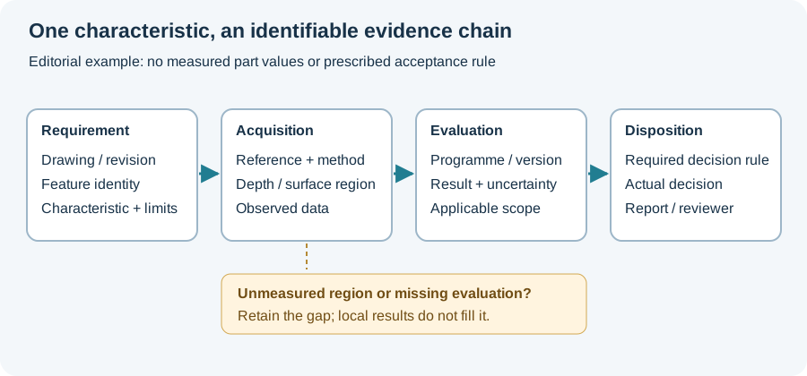
The diagram below follows the feature through data acquisition and evaluation. Use the worksheet to expose a missing link before comparing instrument quotations. Continue to straightness for the geometry question or uncertainty for the result-specific evaluation.
Revision note
October 8, 2026: revised the technical explanation and connected reading after source review. Original publication date and URL retained.