An exit offset tells you where a hole emerges. Deep hole drilling straightness concerns the geometry evaluated along the bore. The distinction matters when a report shows only entry and exit observations but its conclusion describes the entire drilled length.
Equal endpoints can conceal different paths
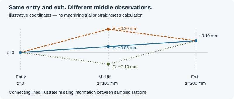
Consider three deliberately invented bore-centre paths. The numbers below are lateral x-coordinates in one fixed reference system, in millimetres. They illustrate information loss; they are not measured machining results or a standards-based straightness calculation.
| Axial depth z | Path A | Path B | Path C |
|---|---|---|---|
| 0 mm | 0.00 | 0.00 | 0.00 |
| 100 mm | 0.05 | 0.20 | -0.10 |
| 200 mm | 0.10 | 0.10 | 0.10 |
All three share the same entry and exit coordinates. Path A’s sampled points lie on a tilted straight line. Paths B and C have different intermediate offsets. If only the endpoints were measured, this table could not be reconstructed. Conversely, three sampled positions still leave the paths between them unobserved.
A tilted line can also raise a datum-related direction or position question. Do not substitute an exit offset for either the drawing’s geometric definition or its evaluation procedure.
Establish what “axis” means in the report
A bore-surface data set does not label its own axis. The report needs to explain the observed surface regions, the construction or fitting used to obtain centres or an axis, and the length included in the evaluation. Where a datum is relevant, identify the datum features and how they were established.
Two reports can use different sampling and evaluation conventions. Comparing their headline deviation alone hides that difference. Start with the actual measurement definition and settings; preserve the underlying observations when available. The GUM, section 3.3.2, identifies incomplete definition and nonrepresentative sampling as possible uncertainty sources.
Access arrangements answer part of the question
Long-reach contact measurement and side-looking optical scanning provide different published ways of acquiring internal geometry. An instrument proposal still needs an access and sampling plan for the required length. The manufacturer’s description is a starting point for that plan, not an uncertainty statement for the reader’s component.
Ask to see the evaluated regions alongside the geometric result. If a report combines observations from opposite ends or different fixtures, it should explain how those observations share a reference. If the middle remains inaccessible, record that gap explicitly rather than interpolating it into a verified path.
Use endpoint evidence at its actual scope
An exit-location series can be useful in alignment investigation: it records whether a production observation repeats. Keep part orientation, entry position and tool/setup identity with each result. It cannot independently determine whether a repeatable offset arose from entry position, direction or changes deeper in the bore.
Release the part against its specified characteristic using the agreed inspection and decision procedure. The next practical question is whether the chosen measurement method provides the required coverage, followed by the uncertainty statement attached to that result.
Combine access routes through an explicit reference
If a long bore is inspected from both ends, identify the common reference used to relate the two acquisitions. Separate local centre observations from the calculation that combines them. Overlapping data can help examine that relationship; the report still needs to describe its evaluation.
An unmeasured middle region remains a coverage gap even if the two accessible ends agree. The figure below retains the assumed paths from the table. Use it to distinguish endpoint agreement, intermediate observations and a full characteristic evaluation before reviewing the measurement proposal.
Revision note
October 8, 2026: revised the technical explanation and connected reading after source review. Original publication date and URL retained.