A setup proposal needs to identify the workpiece, the tool assembly and the circuits serving their different functions. The word “pressure” is incomplete without the connection and purpose of the quoted value.
Identify the relative references
Retain the part location, entry and exit access, tube support and tool mounting in the actual layout. A family-level tool offer does not show whether the selected assembly can travel through the required region and return under its applicable procedure.
The proposed workholding should identify the component state used for both machining and final inspection. If the part is measured in another arrangement, retain that transfer rather than assuming the setup itself establishes the delivered characteristic.
Control and process supply differ
The OMEGA documentation describes RETRAC and international control systems with different actuation arrangements. Its German counterpart gives the corresponding tool-control alternatives. These are named configurations, not interchangeable pressure cycles.
Identify the connections and controlled function in the supplied assembly. Process-fluid delivery and hydraulic tool activation should remain distinguishable in the proposal, even where an installation shares equipment or media.
Other rolling architectures need their own supply review
ECOROLL’s hydrostatic-tool technical account discusses a pressure-supported ball and the associated supply unit. That arrangement does not establish the circuit of every mechanically supported cylinder rolling head.
Use the applicable selected-tool documents for flow, filtration and operating conditions; a page that returns only navigation cannot supply numerical pump or filter prescriptions.
Connect the layout to inspected output
For an assumed trial, retain which setup relationship and circuit condition changed, then the inspected characteristic and region. If several changes occur together, describe the combined setup. The final acceptable reading cannot isolate a workholding effect from a simultaneous tool or fluid change.
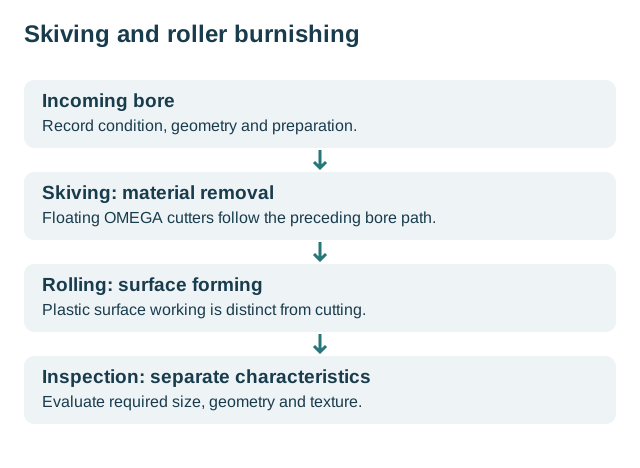
The stages figure below locates the operations that need the configured installation. Use the RFQ worksheet to request its supplied scope. Continue to OMEGA geometry for the head/control distinction or troubleshooting for event-specific evidence.
Revision note
October 8, 2026: revised the technical explanation and connected reading after source review. Original publication date and URL retained.