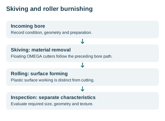
Skiving stock allowance is a decision about the incoming bore and the selected cutting arrangement. A single allowance value cannot define that arrangement if the starting geometry, tool stages and required finished diameter remain unspecified.
Give each stage its own task
ECOROLL’s cylinder-processing description separates the skiving task from surface smoothing by roller burnishing. Its OMEGA product page also distinguishes combinations with additional drilling stages. These are descriptions of named tool arrangements, not interchangeable specifications for every cylinder tube.
When comparing proposals, identify whether the quote starts with an existing bore, includes an earlier material-removal operation, or assumes a supplied pre-machined condition. Otherwise two offers labeled ‘skiving and burnishing’ may cover different work.
Check the incoming path as well as size
In a manufacturer-authored article dated October 17, 2024, Oliver Maiß explains that the skiving arrangement follows the existing bore and does not sustainably correct its prior path deviation. The useful implication is to review the incoming geometric record before expecting the finishing route to resolve an axis problem.
Our proposed preparation record therefore pairs incoming dimensions and measurement locations with the required final geometry. It also identifies which preceding operation is responsible for the condition being supplied. Final surface quality should not be used as a substitute for that geometric record.
Ask for an application specification, not a generic number
Request the selected tool’s allowance recommendation for the supplied material and bore condition, including which stage removes the stock. Retain radial or diametral units exactly as specified; the word ‘allowance’ alone leaves that distinction open.
The reviewed public pages do not establish a universal stock allowance. A trial should compare the delivered bore to its drawing requirements and record the actual incoming condition. Continue to finishing-method selection when the whole route is undecided, or skiving and burnishing versus honing for the broader comparison.
Radial and diametral differences: an assumed calculation
Suppose an invented circular incoming diameter is 79.60 mm and the proposed cutting diameter is 80.00 mm. Their diametral difference is 0.40 mm; the radial difference is 0.20 mm. These are arithmetic teaching inputs, not recommended stock or a validated preparation condition.
The calculation assumes concentric circles. An actual bore with a varying centre path or local form needs a geometric assessment; subtracting two nominal diameters does not establish the available stock at every location. Nor does that subtraction identify a later forming stage’s dimensional effect.
Attach the supplied measurement locations and selected cutting stage to the application recommendation. The stage diagram below connects incoming condition and material removal. Continue to OMEGA geometry for the floating construction or parameters for distinguishing a selected application value from a conversion.
Revision note
October 8, 2026: revised the technical explanation and connected reading after source review. Original publication date and URL retained.