OMEGA identifies an ECOROLL tooling construction. Its floating cutters, preceding cutting stages and retraction mechanism should be read as parts of a named assembly, rather than a set of features shared by every skiving head.
What the product description identifies
The OMEGA page describes cutters supported to float together radially, with a cone involved in diameter adjustment and activation. It also describes cutter assemblies with sequential cutting inserts and combinations containing additional drilling stages.
The corresponding German page distinguishes named two-, three- and four-stage configurations. Establish which one is proposed before interpreting a statement about its incoming bore or delivered task. A feature from one configuration cannot be assumed to exist on another merely because both use the family name.
Floating does not establish a new bore axis
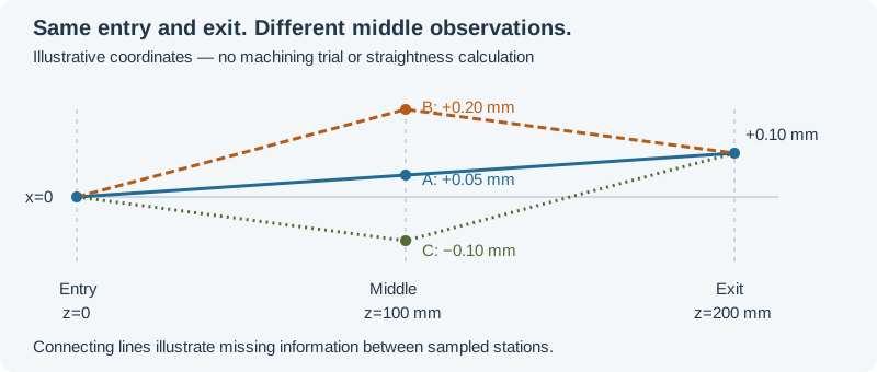
In its October 17, 2024 article, ECOROLL says the floating arrangement follows the prior bore. Read that boundary alongside claims about cutting or surface results. The path diagram below illustrates why a local size or endpoint result can leave intervening geometry open; its coordinates are invented explanatory values.
Retain the incoming bore-path evidence when the required geometry depends on it. An added preceding drilling stage also needs its own identified task rather than borrowing the skiving stage’s claim.
Control interface is part of the assembly
The product pages describe RETRAC and international control arrangements with different actuation locations and pressure-state sequences. A supplier proposal therefore needs the exact tool, tube connection and control arrangement. Those alternatives should not be merged into one generic retraction programme.
Published EN and DE entries also differ on a RIOF length boundary. This review does not use either number as a universal installation limit. Resolve the applicable controlled product specification when making that selection.
Separate explanation from adjustment instructions
A diagram of stage roles can explain the principle, but cannot supply the selected assembly’s cutter offsets, allowance or activation commands. Retain the application document and inspect the actual delivered bore against the required characteristic.
Use the RFQ worksheet for the head and interface identity. Continue to stock allowance for the incoming condition, or setup for the separate mounting, guidance and control relationships. No family-wide centreline correction or universal cutter setting is claimed here.
Revision note
October 8, 2026: revised the technical explanation and connected reading after source review. Original publication date and URL retained.