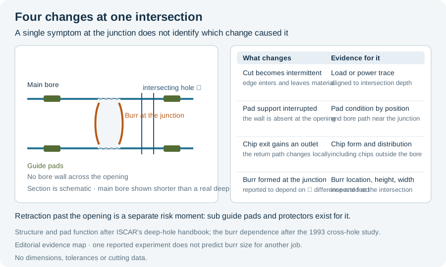
A cross hole changes four things at once: the cut becomes intermittent, the tool’s radial support is interrupted, the chip has somewhere else to go, and a new burr is created at the junction. Reported as one symptom — “it went wrong at the cross hole” — these are indistinguishable. This page separates them and states what has to be recorded before a cause is assigned.
Four effects, four different observations
| What changes | Physical cause | Observation that belongs to it |
|---|---|---|
| Cutting force | The cutting edge enters and leaves material instead of cutting continuously | Force, power or spindle-load trace around the intersection depth |
| Guide pad support | The bore wall the pads bear against is absent across the opening | Pad condition, and any change in bore path or size near the intersection |
| Chip exit | The return path gains an alternative outlet at the opening | Chip form and distribution, and whether chips appear outside the bore |
| Junction geometry | A burr is formed where the two holes intersect | Burr location, height and width, inspected at the junction |
The four columns are the reason there is no single “cross-hole problem”. A tool that breaks at an intersection may have lost guidance, may have been overloaded by the interrupted cut, or may have been retracted through a burr it created. Those have different remedies, and the trace and the pad will usually tell them apart.
The interrupted cut is a load change, not a machining method
“Interrupted cut” in this context is mechanical, not a strategy. The cutting edge meets material, then air, then material again. What a shop can do about it is largely a matter of tool designation, because the countermeasure lives in the drill head’s profile rather than in the machine’s settings.
ISCAR’s deep hole drilling handbook makes that explicit in its drilling-head profile table. Among the standard gundrill head profiles:
- Profile H is stated as suitable for cast iron (usually coated) and aluminium alloys and can be used for cross drilling, angular entry or exit and for interrupted cut, with large coolant gaps between pads.
- Profile I is stated as used for aluminium and brass for best hole finish, and for intersecting holes and interrupted cut or when extra outer diameter support and burnishing is required.
Both statements are the manufacturer’s application guidance for its own head profiles. They describe what the tool is designated for; they do not establish a cutting parameter or a guaranteed result.
Two things follow. First, if the drawing contains an intersection, the head profile is a specification item — a head profiled for continuous cutting is not interchangeable with one profiled for cross drilling, even at the same diameter. Second, the profile is fixed when the tool is manufactured: the same handbook notes that although regrinding may change the cutting geometry, the profile should remain the same. A regrind that alters the profile invalidates the reason the head was chosen.
Support is lost exactly where it is needed
Deep-hole tooling guides itself from the bore it has just produced. The “classical” asymmetrical tools transfer part of the cutting forces through guide pads to the bore wall, which is what holds the tool on course. At an intersection, part of that wall is not there.
This is a design requirement, not only an operating caution, and the tool catalogues show it. Alongside full guide pads, the same ISCAR head family carries sub guide pads, given as helping prevent breakage while pulling out the tool from hole/cross-hole processing. Those sub guide pads are made from soft steel specifically to avoid damaging the surface. The same catalogue lists a filler that protects the guide-pad pocket from damage when drilling, and a protector that prevents damage to the guide pad when retracting the tool after drilling.
Read together, these parts describe a tool being protected in three separate moments: while cutting, during retraction, and against the pocket itself. Retraction is named as its own risk moment in both the sub-guide-pad and protector entries. That is a useful correction to a common assumption — that the danger at a cross hole lies only in the entry shock.
For the geometry side of this — separating a diameter change from a bore-path change and checking what was actually measured — continue with Deep Hole Geometry Diagnosis.
The burr at the junction is material- and feed-dependent
A machined burr forms inside the main bore where the intersecting hole breaks through. A Japanese study of exactly this case gives the factors that move it, and they are unusually specific for a burr question.
Ohshima, Maekawa and Murata, Burr Formation and Deburring in Drilling Cross Holes, Journal of the Japan Society for Precision Engineering, 1993, reports:
- Material order. Both burr height and burr width were small in the order free-cutting steels, commercial aluminium, low carbon steel (SS400).
- Geometry and feed. Burr generation depended on the diameter difference between the main hole and the intersecting hole, and on the feed rate at the end of drilling.
- A self-clearing effect. The burrs were decreased by the penetration of the crossed hole, through the moving chips inside the main hole.
- Deformatting, not just cutting, in the removal method. Using ball burnishing to remove the burrs, the removal rate reached 89% for the leaded resulphurized steel but decreased to 45% for the aluminium.
- Orientation matters. Both the drilling direction and the rolling direction of the workpiece material influenced burr formation and the deburring characteristics.
These are the stated results of one 1993 experiment on the materials and conditions it used. They are not a general burr-height prediction, and the removal-rate percentages belong to the ball-burnishing method tested, not to deburring in general.
The third finding deserves attention because it is counter-intuitive in a useful way: chip movement through the main bore reduced the burr rather than aggravating it. That means a cross-hole burr problem and a chip-evacuation problem can interact, and that a change made to improve chip exit can move the burr result as well. Do not treat the two as independent.
What to record before assigning a cause
A cross-hole incident record needs more than the symptom. The evidence above identifies the fields:
- Position and orientation. Exact depth and angular position of the intersection; the drilling direction relative to the workpiece’s rolling direction where the material is rolled.
- Diameter relationship. Main bore diameter and intersecting hole diameter, since the difference is reported to govern burr formation.
- The end-of-drilling condition. Feed at the point where the tool reached and left the intersection, including whether feed was changed there.
- Traces aligned to depth. Force, power or load around the intersection, so the interrupted cut can be seen rather than inferred.
- Pad and tool condition, by position. Which pad shows what, and at which moment the damage is suspected — cutting through, or retracting.
- Retraction path. Whether the tool was withdrawn through the junction, and how.
- Chip evidence. Form and location of chips around the intersection, including chips found outside the bore.
Use the incident record worksheet to hold those fields against one event, and start from Deep Hole Drilling Symptoms to route the observation to the narrower investigation.
Sources and limits
- Ikuya Ohshima, Katsuhiro Maekawa, Ryoji Murata, “Burr Formation and Deburring in Drilling Cross Holes”, Journal of the Japan Society for Precision Engineering, 1993, Vol. 59, No. 1, pp. 155–160, DOI 10.2493/jjspe.59.155. Article record. Abstract read 11 October 2026. The findings above rest on the paper’s abstract; no experimental condition, statistic or author-stated limit beyond them is reproduced here, and the burr figures carry no general prediction.
- ISCAR, Drilling Handbook (Deep Hole Drilling section). Standard gundrill head profiles, Table 6.11.1.2 (Profile H: cross drilling, angular entry or exit, interrupted cut; Profile I: intersecting holes and interrupted cut; profile fixed at manufacture); drilling head design and the sub guide pad; filler and protector functions. Read 11 October 2026. Manufacturer application guidance for its own products, retained as attribution.
- What this page does not assert. No cutting parameter, feed change, tool designation or recovery procedure is given. The two effects above are described as designations and reported findings, not as settings for a particular job.