A chip sample describes material removed during an identified interval. Its diagnostic value falls when chips from different bores, depths or tool conditions are mixed. Deep hole drilling chip morphology should begin with sample identity, then examine which process observations accompany the change.
A defined comparison rather than a shape catalogue
In their 2024 study, Tamura and Matsumura compare chips from successive holes made with a 6 mm, two-flute TiCN-coated HSS drill. The 40 mm blind-hole experiment used 0.5% carbon steel and dry conditions. It therefore cannot establish ideal chip forms for every wet gun-drilling or BTA application.
The authors observed changes around the lip ends and margins as wear progressed, together with a change in curled-chip form. Their analysis relates more radial chip flow to smaller curl pitch and greater interference with the evacuation route. That is a mechanism interpretation within the studied tool and conditions, not a visual code that uniquely diagnoses another process.
Record where the sample came from
An editorial sample record identifies part and bore, collection point and interval, tool/service state, material condition and relevant commands. A sample collected at the return outlet need not preserve the original formation state unchanged. Keep that location explicit rather than calling every sample a direct view of the cutting edge.
Photographs benefit from scale and a consistent view. Keep the original sample or image linked to the record where the site’s collection procedure allows it. Do not combine chips from an earlier accepted interval with a later fault merely because they were in the same tray.
Compare changes with other evidence
For a change in chip form, review the edge condition and time-aligned force or fluid observations. The published study used physical and measured evidence together. A photograph alone cannot establish whether delivery, geometry or material condition changed first.
Record the observed dimensions and form in plain language before assigning a cause. If the sequence remains unresolved, preserve that uncertainty rather than inserting an unsupported material-wide chip classification.
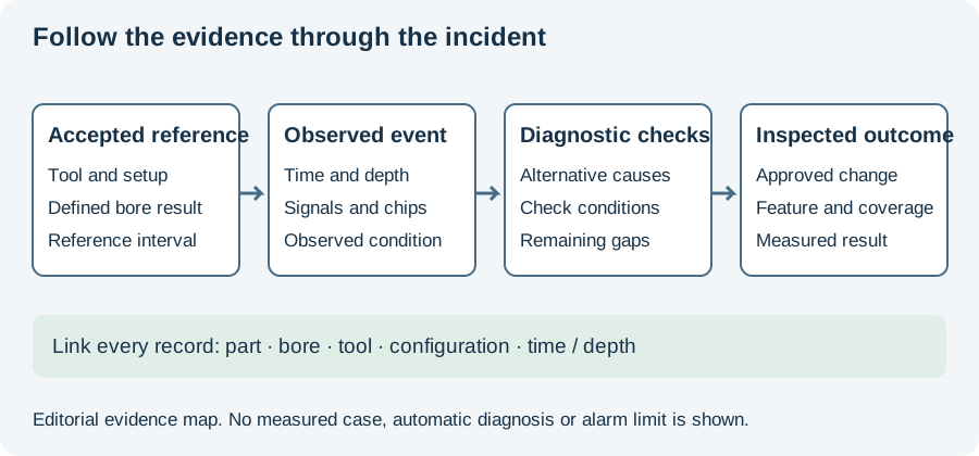
The incident timeline below shows where sampled chips sit beside tool and inspection evidence. Use the worksheet to keep the interval identifiable. Continue to wear analysis for the studied sequence, or chip evacuation for the supply and return paths of the installed method.
Revision note
October 8, 2026: revised the technical explanation and connected reading after source review. Original publication date and URL retained.