Deep hole drilling tool wear becomes a stronger diagnosis when edge observations, chip samples and force records describe the same sequence. A 2024 experiment by Tamura and Matsumura provides such a sequence for a particular twist drill. Its conditions limit how the findings can be used elsewhere.
The full experimental scope
The J-STAGE paper reports non-step drilling of 40 mm blind holes in 0.5% carbon steel with a 6 mm, two-flute TiCN-coated high-speed-steel drill. Table 1 specifies dry lubrication conditions. This is not an internally cooled gun-drill or BTA test.
The authors measured thrust and torque, examined the drill and chips, and measured bore profiles and roughness. Those separate observations let the study examine how an evolving tool relates to the delivered surface rather than using a force change as the only wear evidence.
What changed during the sequence
The reported observations include margin coating loss and adhesion, different curled-chip form, increased force oscillation and deterioration of the measured bore. The authors’ analysis attributes a more radial chip-flow direction to geometry changes around the lip ends and margins of the worn drill, relating that flow to restricted evacuation.
Keep observation and interpretation distinct: the photographed edge and chips are physical findings; the cutting model is part of the explanation. Their agreement in this defined experiment does not supply a unique signal signature for every tool.
A load increase can contain several contributions
The paper separates reference cutting, wear-related and clogging-related contributions using measurements at different drilling depths. That makes a useful investigation point: a rising trace need not represent only edge wear. Another operation would need its own evidence before making that separation.
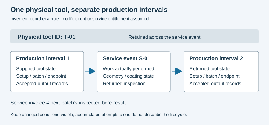
For the reader’s incident, attach the removed edge photograph to its service interval, the last accepted bore and the event that prompted removal. Record whether chip observations and inspection came from that same interval. A later photograph cannot establish exactly when damage began.
Service disposition remains tool-specific
Use the selected tool’s applicable inspection and service criteria for reuse, regrinding or rejection. The dry experiment supplies no universal flank-wear threshold or torque alarm for a gun drill.
The service-interval diagram below identifies which observations belong together. Use the incident worksheet for the timeline, then continue to chip sampling or tool lifecycle records according to the unresolved question.
Revision note
October 8, 2026: revised the technical explanation and connected reading after source review. Original publication date and URL retained.